OIL PUMP (w/ DPF) REMOVAL

Note
-
When replacing the injectors (including shuffling the injectors between the cylinders), common rail or cylinder head, it is necessary to replace the injection pipes with new ones.
-
When replacing the fuel supply pump, common rail, cylinder block, cylinder head, cylinder head gasket or timing gear case, it is necessary to replace the fuel inlet pipe with a new one.
-
After removing the injection pipes, clean them with a brush and compressed air.
-
REMOVE ENGINE ASSEMBLY
-
INSTALL ENGINE STAND
-
Install the engine to an engine stand with the bolts.
-
Remove the engine sling device and chain block.
-
Remove the 2 bolts and 2 engine hangers.
-
-
REMOVE VANE PUMP ASSEMBLY
-
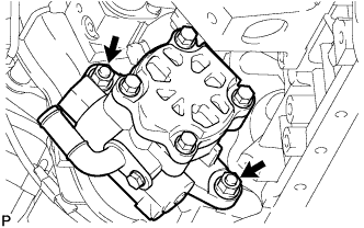
Remove the 2 nuts and the vane pump assembly.
-
Remove the vane pump O-ring from the vane pump assembly.
-
-
REMOVE VACUUM PUMP ASSEMBLY
-
Remove the 2 nuts and the vane pump assembly.
-
Remove the vane pump O-ring from the vane pump assembly.
-
-
REMOVE TIMING BELT
-
REMOVE NO. 1 TIMING BELT IDLER SUB-ASSEMBLY
-
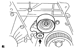
Using a 10 mm hexagon wrench, remove the bolt, No. 1 timing belt idler and washer.
-
-
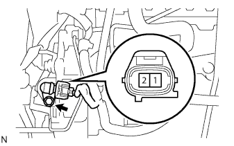
REMOVE CRANKSHAFT POSITION SENSOR
-
TYPE A:
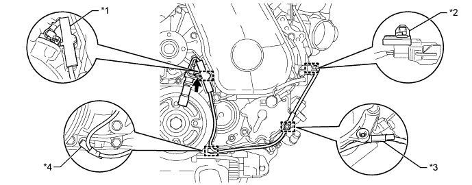
Text in Illustration *1 Clamp *2 Wire Harness Clamps (A) *3 Wire Harness Clamps (B) *4 Wire Harness Clamps (C)
-
Detach the 2 wire harness clamps (B, C).
-
Disconnect the crankshaft position sensor connector.
-
Detach the crankshaft position sensor connector from the No. 1 vacuum transmitting pipe.
-
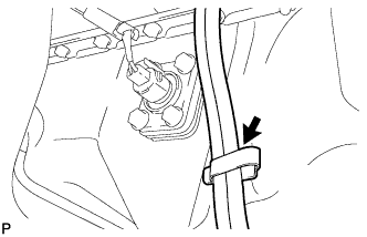
Remove the clamp.
Note
-
Make sure that no portion of the clamp remains in the clamp installation hole. If there is any portion of the clamp remaining, remove it.
-
Do not reuse the clamp.
-
-
Remove the bolt and crankshaft position sensor.
-
Remove the wire harness clamp (A) from the crankshaft position sensor.
-
-
TYPE B:
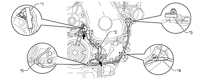
Text in Illustration *1 Clamp *2 Bracket (Clamp) *3 Wire Harness Clamps (A) *4 Wire Harness Clamps (B) *5 Wire Harness Clamps (C) - -
-
Detach the 2 wire harness clamps (B, C).
-
Disconnect the crankshaft position sensor connector.
-
Detach the crankshaft position sensor connector from the No. 1 vacuum transmitting pipe.
-
Remove the clamp.
Note
-
Make sure that no portion of the clamp remains in the clamp installation hole. If there is any portion of the clamp remaining, remove it.
-
Do not reuse the clamp.
-
-
Remove the bolt and bracket (clamp).
-
Remove the bolt and crankshaft position sensor.
-
Remove the wire harness clamp (A) from the crankshaft position sensor.
-
Detach the 2 wire harness clamps from the bracket (clamp).
-
-
-
REMOVE CAMSHAFT POSITION SENSOR
-
Disconnect the camshaft position sensor connector.
-
Remove the bolt and the camshaft position sensor.
-
-
REMOVE OIL PRESSURE SWITCHING VALVE ASSEMBLY
-
Disconnect the oil pressure switching valve connector.
-
Remove the bolt and oil pressure switching valve.
-
-
REMOVE DIESEL THROTTLE BODY ASSEMBLY
-
REMOVE ELECTRIC EGR CONTROL VALVE ASSEMBLY
-
REMOVE EGR COOLER WITH NO. 2 EGR VALVE ASSEMBLY
-
REMOVE COMMON RAIL ASSEMBLY
-
REMOVE FUEL SUPPLY PUMP ASSEMBLY
-
REMOVE INJECTOR ASSEMBLY
-
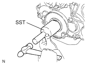
REMOVE CAMSHAFT TIMING PULLEY
-
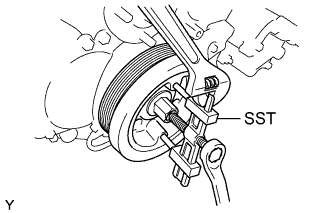
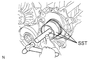
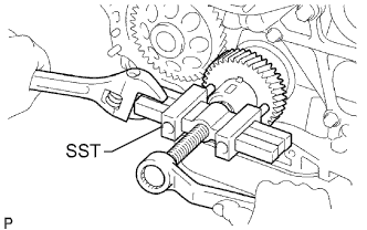
Remove the bolt of the camshaft timing pulley while holding the camshaft with a wrench.
-
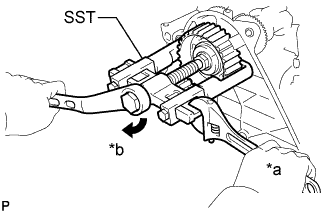
Text in Illustration *a Hold *b Turn Using SST, remove the camshaft timing pulley and key.
- SST
- 09950-40011 ( 09951-04010, 09952-04010, 09953-05010, 09957-04010 )
- 09955-04150
-
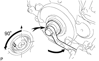
Rotate the crankshaft approximately 90° counterclockwise from TDC to lower the piston.
-
-
REMOVE NO. 2 TIMING BELT COVER
-
Remove the nut, 4 bolts and No. 2 timing belt cover.
-
-
REMOVE WATER PUMP ASSEMBLY
-
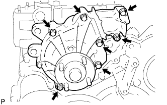
Remove the 5 bolts, 2 nuts, water pump and gasket.
-
-
REMOVE CRANKSHAFT PULLEY
-
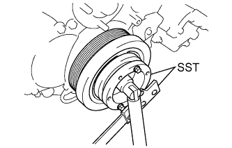
Using SST, hold the crankshaft pulley and loosen the pulley bolt.
- SST
- 09213-58014
- 09330-00021
-
Using SST, remove the pulley bolt and crankshaft pulley.
- SST
- 09950-50013 ( 09951-05010, 09952-05010, 09953-05020, 09954-05021 )
-
-
REMOVE OIL PAN SUB-ASSEMBLY
-
Disconnect the vinyl tube from the oil pan.
-
Remove the 22 bolts and 2 nuts.
-
w/ DPF:
Insert the blade of an oil pan seal cutter between the oil pan and cylinder block, cut through the applied sealer, and then remove the oil pan.
Note
-
Do not use the oil pan seal cutter for the area between the oil pan and timing gear case, or for the area between the oil pan and rear oil seal retainer.
-
Be careful not to damage the oil pan flange.
-
-
w/o DPF:
Insert the blade of an oil pan seal cutter between the oil pan and cylinder block stiffening plate, cut through the applied sealer, and then remove the oil pan and cylinder block stiffening plate.
Note
-
Do not use the oil pan seal cutter for the area between the oil pan and timing gear case, or for the area between the oil pan and rear oil seal retainer.
-
Be careful not to damage the oil pan flange.
-
-
-
REMOVE OIL STRAINER SUB-ASSEMBLY
-
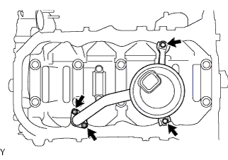
Remove the 2 bolts, 2 nuts, oil strainer and gasket.
-
-
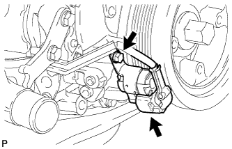
REMOVE TIMING GEAR COVER
-
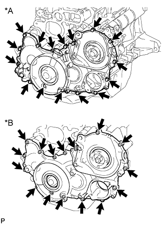
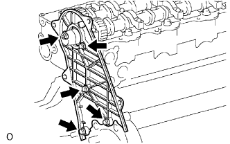
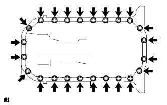
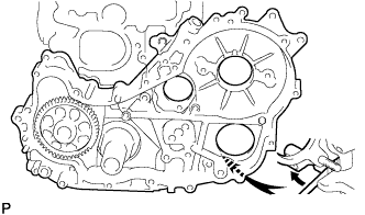
Text in Illustration *A w/ DPF *B w/o DPF Remove the 14 bolts and 2 nuts.
-
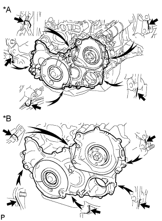
Text in Illustration *A w/ DPF *B w/o DPF Pry the timing gear cover at the locations shown in the illustration and remove the timing gear cover.
Note
Be careful not to drop the injection gear.
-
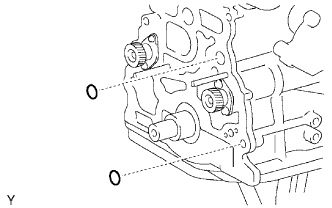
w/ DPF:
Remove the 3 O-rings from the timing gear case.
-
w/o DPF:
Remove the O-rings from the timing gear case.
-
-
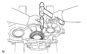
REMOVE TIMING GEAR CASE OIL SEAL
Tech Tips
There are 2 methods to remove the oil seal.
-
If the timing gear cover is removed from the cylinder block:
-
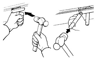
Using a screwdriver and hammer, tap out the oil seal.
-
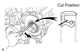
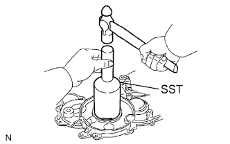
Using SST and a hammer, tap in a new oil seal until its surface is flush with the timing gear cover edge.
- SST
- 09223-15020
- 09502-12010
- 09950-70010 ( 09951-07100 )
-
Apply MP grease to the lip of the oil seal.
-
-
If the timing gear cover is installed to the cylinder block:
-
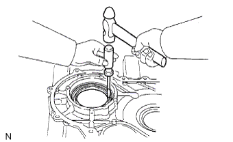
Using a knife, cut through the lip of the oil seal.
-
Using a screwdriver, pry out the oil seal.
Note
Be careful not to damage the crankshaft.
-
Apply MP grease to the lip of the oil seal.
-
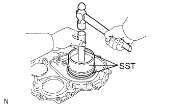
Using SST and a hammer, tap in a new oil seal until its surface is flush with the timing gear cover edge.
- SST
- 09223-15020
- 09502-12010
- 09950-70010 ( 09951-07100 )
-
-
-
REMOVE TIMING GEAR COVER OIL SEAL
Tech Tips
There are 2 methods to remove the oil seal.
-
If the timing gear cover is removed from the cylinder block:
-
Using a screwdriver and hammer, tap out the oil seal.
-
Using SST and a hammer, tap in a new oil seal until its surface is flush with the timing gear cover edge.
- SST
- 09214-76011
-
Apply MP grease to the lip of the oil seal.
-
-
If the timing gear cover is installed to the cylinder block:
-
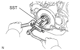
Using SST, remove the oil seal.
- SST
- 09308-10010
- 09950-40011 ( 09957-04010 )
- 09950-60010 ( 09951-00350 )
-
Apply MP grease to the lip of a new oil seal.
-
Using SST and a hammer, tap in the oil seal until its surface is flush with the timing gear cover edge.
- SST
- 09214-76011
-
-
-
REMOVE INJECTION GEAR
-
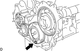
Secure the No. 2 idle sub gear to the No. 1 idle gear with a service bolt.
- Torque:
- 8.0 N*m { 82 kgf*cm, 71 in.*lbf }
Note
If the bolt hole of the No. 2 idle sub gear is not aligned with the bolt hole of the No. 1 idle gear, rotate the crankshaft counterclockwise to align the bolt holes. Then install the service bolt.
-
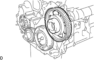
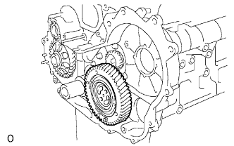
Remove the injection gear.
-
-
REMOVE NO. 1 CRANKSHAFT POSITION SENSOR PLATE
-
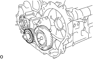
Remove the No. 1 crankshaft position sensor plate.
-
-
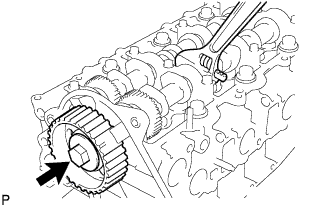
REMOVE CRANKSHAFT TIMING GEAR
-
Using SST, remove the crankshaft timing gear.
- SST
- 09950-50013 ( 09951-05010, 09952-05010, 09953-05010, 09954-05021 )
-
-
REMOVE IDLE GEAR THRUST PLATE
-
Remove the 2 bolts and idle gear thrust plate.
-
-
REMOVE NO. 1 IDLE GEAR
-
Remove the No. 1 idle gear together with the No. 1 and No. 2 idle sub gears.
-
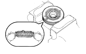
Mount the No. 1 idle gear and No. 2 idle sub gear in a vise.
Note
Be careful not to damage the gears.
-
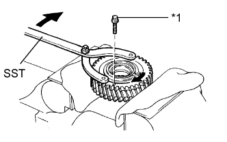
Text in Illustration *1 Service Bolt Using SST, turn the No. 1 idle sub gear clockwise and remove the service bolt.
- SST
- 09960-10010 ( 09962-01000, 09963-00600 )
-
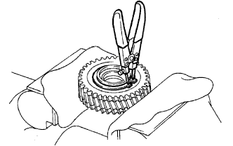
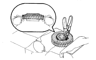
Using snap ring pliers, remove the shaft snap ring.
-
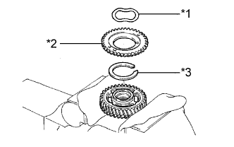
Text in Illustration *1 Wave Washer *2 No. 1 Idle Sub Gear *3 Idle Gear Spring Remove the wave washer, No. 1 idle sub gear and idle gear spring.
-
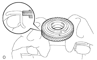
Remove the No. 1 idle gear and set it in a vise.
Note
Be careful not to damage the gear.
-
Using snap ring pliers, remove the shaft snap ring.
-
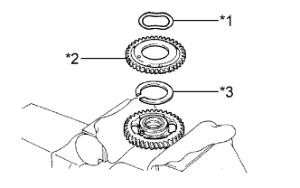
Text in Illustration *1 Wave Washer *2 No. 2 Idle Sub Gear *3 Idle Gear Spring Remove the wave washer, No. 2 idle sub gear and idle gear spring.
-
-
REMOVE NO. 1 IDLE GEAR SHAFT
-
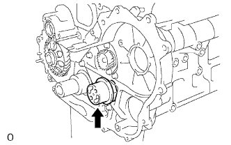
Remove the No. 1 idle gear shaft.
-
-
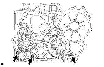
REMOVE TIMING GEAR CASE ASSEMBLY
-
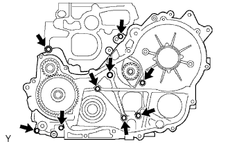
Remove the union bolt and 8 bolts.
-
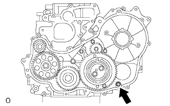
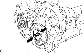
Pry the timing gear case at the location shown in the illustration and remove the timing gear case.
-
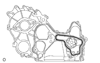
Remove the gasket.
-
Remove the 2 O-rings.
-