OIL PUMP (w/o DPF) REMOVAL

-
PLACE FRONT WHEELS FACING STRAIGHT AHEAD
-
DISCONNECT CABLE FROM NEGATIVE BATTERY TERMINAL
-
REMOVE FRONT WHEELS
-
DRAIN ENGINE COOLANT
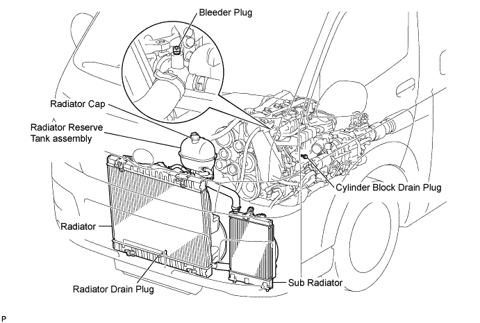
CAUTION:
To avoid the danger of being burned, do not remove the radiator reserve tank cap while the engine and radiator are still hot. Thermal expansion will cause hot engine coolant and steam to blow out from the radiator.
-
Loosen the radiator drain plug (on the radiator).
-
Remove the radiator cap.
-
Loosen the engine drain plug (on the engine oil cooler cover), and drain the coolant.
-
Tighten the engine drain plug (on the radiator).
-
Tighten the engine drain plug (on the engine oil cooler cover).
- Torque:
- 8.0 N*m { 82 kgf*cm, 71 in.*lbf }
-
-
DRAIN ENGINE OIL
-
Remove the oil filler cap.
-
Remove the drain plug from the oil pan and drain the engine oil into a container.
-
Clean the drain plug.
-
Install the drain plug with a new gasket.
- Torque:
- 34 N*m { 347 kgf*cm, 25 ft.*lbf }
-
-
REMOVE FRONT SEAT ASSEMBLY RH
-

Move the front seat assembly fully forward.
-
Remove the 2 bolts on the rear side of the seat.
-
Move the front seat assembly to the rearmost position.
-
Remove the 2 bolts on the front side of the seat.
-
Move the front seat assembly to the center of the seat slide rail. Set the seatback in the upright position.
-
Disconnect the front seat inner belt assembly connector.
-
Remove the front seat assembly.
-
-
REMOVE FRONT DOOR SCUFF PLATE RH
-
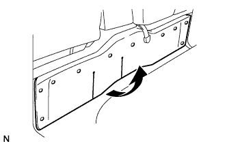
REMOVE ENGINE SERVICE HOLE SUB COVER SUB-ASSEMBLY
-
Roll up the carpet, and remove the engine service hole sub cover assembly.
-
-
REMOVE NO. 2 ENGINE SERVICE HOLE COVER
-
Roll up the carpet.
-
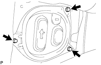
Remove the 3 bolts and No. 2 engine service hole cover.
-
-
LOOSEN FAN PULLEY
-
Loosen the 4 nuts from the fan pulley.
-
-
REMOVE FAN & GENERATOR V BELT
-
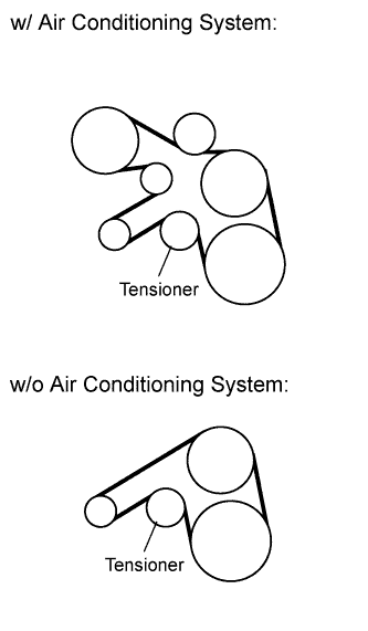
Remove the drive belt by rotating the tensioner pulley clockwise to loosen its tension with the pulley set bolt of the tensioner.
-
-
REMOVE FAN PULLEY
-
Remove the 4 nuts and fan pulley.
-
-
REMOVE FENDER APRON MUDGUARD SEAL RH
-
Disengage the 4 clips and remove the fender apron mudguard.
-
-
SEPARATE TAIL EXHAUST PIPE ASSEMBLY (for Long Wheelbase)
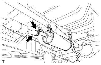
-
Remove the 2 bolts and 2 nuts, and separate the tail exhaust pipe.
-
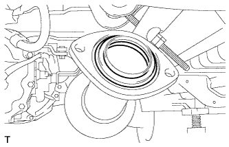
Remove the gasket.
-
-
SEPARATE CENTER EXHAUST PIPE ASSEMBLY (for Super Long Wheelbase)
-
Remove the 2 bolts and 2 nuts, and separate the center exhaust pipe.
-
Remove the gasket.
-
-
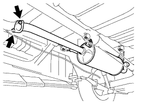
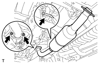
REMOVE FRONT EXHAUST PIPE ASSEMBLY
-
Remove the 2 bolts and the 2 compression springs.
-
Remove the hanger and the front exhaust pipe.
-
Remove the gasket.
-
-
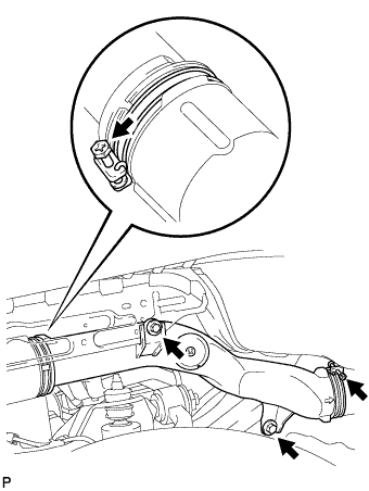
REMOVE COMPRESSOR OUTLET ELBOW
-
Remove the 2 hose clamps, bolt and compressor outlet elbow.
-
-
REMOVE NO. 1 AIR CLEANER HOSE
-
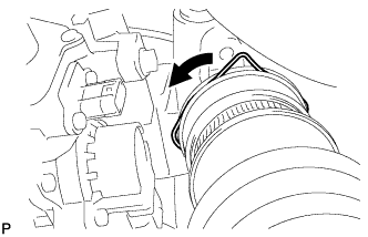
Pull the stopper upward and disconnect the No. 1 air cleaner hose from the compressor inlet elbow.
-
-
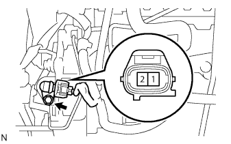
DISCONNECT TURBOCHARGER MOTOR CONNECTOR
-
Disconnect the turbocharger motor connector.
-
-
REMOVE AIR TUBE ASSEMBLY
-
Remove the 2 hose clamps, 2bolts, air tube assembly and No. 1 air cleaner hose.
-
-
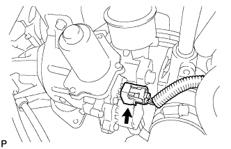
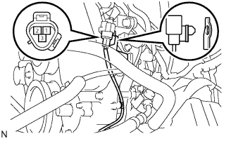
DISCONNECT TURBOCHARGER STROKE SENSOR CONNECTOR
-
Disconnect the turbocharger stroke sensor connector.
-
-
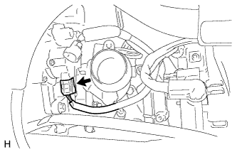
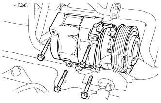
SEPARATE W/ PULLEY COMPRESSOR ASSEMBLY (w/ Air Conditioning System)
-
Disconnect the connector.
-
Remove the 4 bolts and separate the compressor.
-
-
REMOVE NO. 1 COMPRESSOR MOUNTING BRACKET (w/ Air Conditioning System)
-
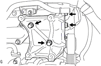
Remove the 4 bolts and compressor bracket.
-
-
REMOVE NO. 2 IDLE PULLEY ASSEMBLY (w/ Air Conditioning System)
-
Remove the bolt, washers and idle pulley assembly.
-
-
REMOVE GENERATOR BRACKET
-
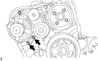
Remove the 2 bolts, then remove the generator bracket.
-
-
REMOVE GENERATOR ASSEMBLY
-
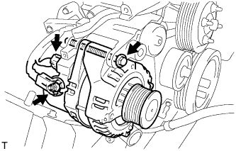
Disconnect the generator connector.
-
Remove the terminal cap.
-
Remove the nut and disconnect the wire harness from terminal B.
-
Remove the bolt and generator.
-
-
REMOVE V-RIBBED BELT TENSIONER ASSEMBLY
-
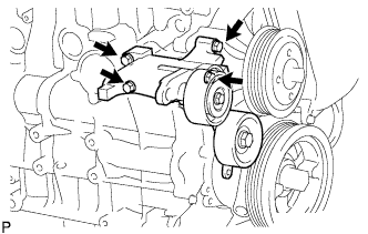
Remove the 4 bolts and belt tensioner assembly.
-
-
REMOVE VENTILATION PIPE SUB-ASSEMBLY
-
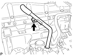
Remove the bolt and ventilation pipe sub-assembly.
-
-
REMOVE NO. 1 TURBO INSULATOR
-
Remove the 2 bolts and turbo insulator.
-
-
REMOVE EXHAUST MANIFOLD HEAT INSULATOR
-
Remove the 2 bolts and No. 1 exhaust manifold heat insulator.
-
-
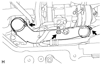
REMOVE NO. 1 TURBO WATER HOSE
-
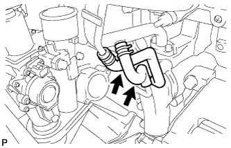
Loosen the 2 clips and disconnect the 2 turbo water hoses.
-
-
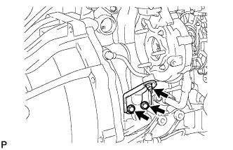
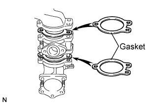
REMOVE TURBINE OUTLET ELBOW
-
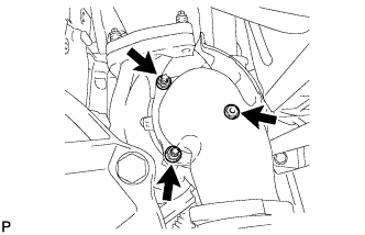
Remove the 3 nuts, turbine outlet elbow and gasket.
-
-
REMOVE TURBOCHARGER STAY
-
Remove the 2 bolts and nut to remove the turbocharger stay.
-
-
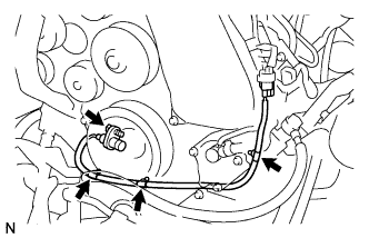
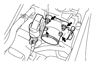
REMOVE TURBO OIL INLET PIPE SUB-ASSEMBLY
-
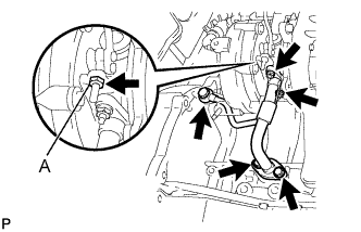
Remove the 2 bolts, 2 nuts and union bolt, then remove the turbo oil inlet pipe sub-assembly and gasket.
Note
Do not loosen the nut labeled A, If mistakenly loosened, replace the turbocharger.
-
-
REMOVE EXHAUST MANIFOLD
-
Remove the 8 nuts and exhaust manifold from the cylinder head.
-
-
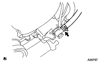
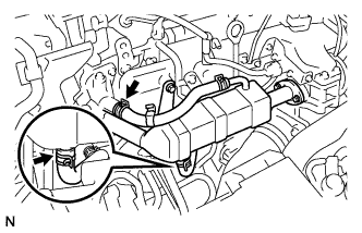
DISCONNECT OIL RETURN HOSE
-
Disconnect the oil return hose from the intake manifold.
-
-
DISCONNECT NO. 4 AIR HOSE
-
Remove the clamp, and disconnect the No. 4 air hose from the diesel throttle body.
-
-
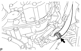
DISCONNECT RADIATOR HOSE INLET
-
Remove the clamp, and disconnect the radiator inlet hose from the water inlet.
-
-
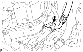
DISCONNECT NO. 4 RADIATOR HOSE
-
Remove the clamp, and disconnect the No. 4 radiator hose from the water outlet.
-
-
DISCONNECT NO. 3 WATER BY-PASS HOSE
-
Remove the clamp, and disconnect the No. 3 water by-pass hose from the water by-pass pipe.
-
-
DISCONNECT NO. 2 FUEL HOSE
-
Remove the clamp, and disconnect the No. 2 fuel hose from the nozzle leakage pipe No. 2.
-
-
DISCONNECT NO. 1 FUEL HOSE
-
Remove the clamp, and disconnect the No. 1 fuel hose from the injection pump assembly.
-
-
DISCONNECT VACUUM HOSE
-
Disconnect the vacuum hose from the vacuum pump assembly.
-
-
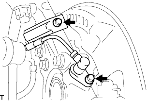
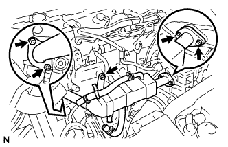
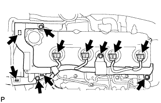
DISCONNECT ENGINE WIRE
-
Remove the wire harness support from the ECM.
-
Disconnect the connectors from the ECM.
-
Disconnect the clamps from the engine wire and earth cable.
-
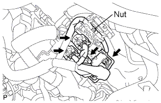
Remove the 4 connectors and nut as shown in the illustration.
-
-
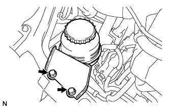
SEPARATE VANE PUMP OIL RESERVOIR ASSEMBLY
-
Remove the 2 bolts, and separate the vane pump oil reservoir assembly.
-
-
REMOVE MANUAL TRANSMISSION UNIT ASSEMBLY (for Manual Transmission)
Refer to the procedures up to "REMOVE MANUAL TRANSMISSION UNIT ASSEMBLY" Click here.
-
REMOVE AUTOMATIC TRANSMISSION ASSEMBLY (for Automatic Transmission)
Refer to the procedures up to "REMOVE AUTOMATIC TRANSMISSION ASSEMBLY" Click here.
-
REMOVE CLUTCH COVER ASSEMBLY (for Manual Transmission)
-
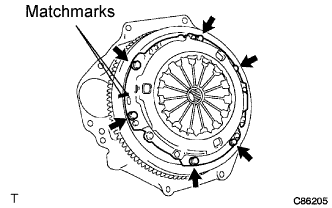
Put matchmarks on the clutch cover assembly and the flywheel sub-assembly.
-
Loosen each set bolt one turn at a time until spring tension is released.
-
Remove the set bolts, and pull off the clutch cover assembly.
Note
Do not drop the clutch disc assembly.
-
-
REMOVE CLUTCH DISC ASSEMBLY (for Manual Transmission)
Note
Keep the lining part of the clutch disc assembly, the pressure plate and surface of the flywheel sub-assembly away from oil and foreign matter.
-
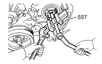
REMOVE FLYWHEEL SUB-ASSEMBLY
-
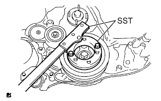
Fix the crankshaft with SST.
- SST
- 09213-58013
- 09330-00021
-
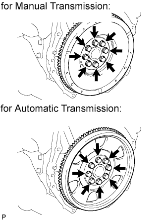
For manual transmission:
Remove the 8 bolts and remove the flywheel.
-
For automatic transmission:
Remove the 8 bolts, and remove the drive plate spacer rear, drive plate and flywheel.
-
-
REMOVE REAR END PLATE
-
Remove the bolt and rear end plate.
-
-
REMOVE SPEED SENSOR FRONT LH (w/ ABS)
-
Remove the 2 bolts, and separate the speed sensor from the steering knuckle.
Note
-
Be careful not to damage the speed sensor.
-
Prevent foreign matter from adhering to the speed sensor.
-
-
-
REMOVE SPEED SENSOR FRONT RH (w/ ABS)
Tech Tips
Use the same procedures described for the LH side.
-
REMOVE FRONT DISC BRAKE CALIPER ASSEMBLY LH
-
Remove the 2 bolts, and disconnect the brake caliper assembly.
Note
Use a wire or an equivalent to keep the brake caliper from hanging down by the flexible hose.
-
-
REMOVE FRONT DISC BRAKE CALIPER ASSEMBLY RH
Tech Tips
Use the same procedures described for the LH side.
-
SEPARATE FRONT SUSPENSION ARM SUB-ASSEMBLY UPPER LH
-
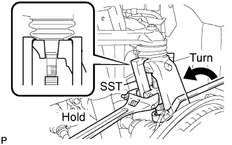
Remove the cotter pin and loosen the nut.
- SST
- 09628-62011
Note
Do not remove the nut.
-
Using SST, separate the steering knuckle from the suspension upper arm and remove the nut.
Note
-
Fix the steering knuckle with a wire so that the flexible hose does not receive excessive force.
-
Do not damage the ball joint dust cover.
-
-
-
SEPARATE FRONT SUSPENSION ARM SUB-ASSEMBLY UPPER RH
Tech Tips
Use the same procedures described for the LH side.
-
SEPARATE SHOCK ABSORBER ASSEMBLY FRONT LH
-
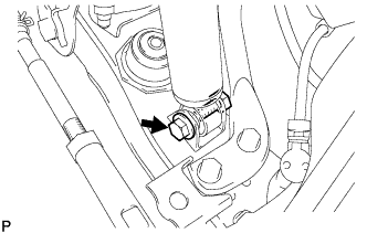
Remove the bolt and separate the front shock absorber from the front suspension lower arm.
-
-
SEPARATE SHOCK ABSORBER ASSEMBLY FRONT RH
Tech Tips
Use the same procedures described for the LH side.
-
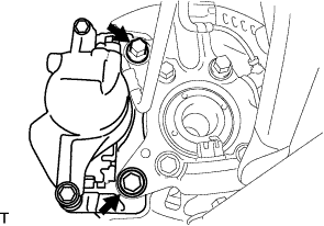
SEPARATE STEERING TORQUE SHAFT ASSEMBLY
-
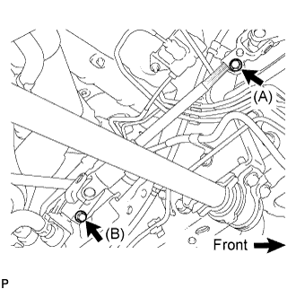
Loosen bolt (A) and remove bolt (B), then slide the steering torque shaft assembly.
Tech Tips
-
Do not remove bolt (A).
-
Do not disconnect the steering torque shaft assembly from the power steering link assembly.
-
-
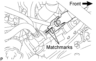
Put matchmarks on the steering torque shaft assembly and the power steering link assembly.
-
Separate the steering torque shaft assembly from the power steering link assembly.
-
-
REMOVE ENGINE ASSEMBLY
-
Using the engine lifter, hold the engine assembly and separate the rear engine mount.
-
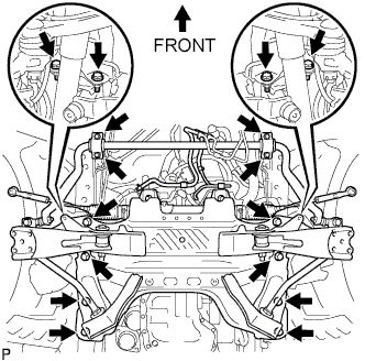
Remove the 16 bolts and remove the stabilizer brackets and front suspension cross member.
-
Remove the engine assembly w/ transmission out of the vehicle slowly and carefully.
-
-
REMOVE ENGINE WIRE
-
Disconnect the engine wire from the engine assembly.
-
-
INSTALL ENGINE HANGERS
-
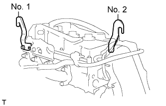
Install the 2 engine hangers in the correct direction.
- Torque:
- No. 1 engine hanger
- 47 N*m { 479 kgf*cm, 35 ft.*lbf }
- No. 2 engine hanger
- 60 N*m { 612 kgf*cm, 44 ft.*lbf }
Parts name Parts No. Engine hanger No.1 upper
Bolt
12284-30020
91512-61014
Engine hanger No.2
Bolt
12282-67020
91642-81030
Note
Use a new bolt for the engine hanger.
-
-
SEPARATE NO. 1 OIL RESERVOIR TO PUMP HOSE
-
Remove the clip and separate the No.1 oil reservoir to pump hose.
-
-
SEPARATE PRESSURE FEED TUBE ASSEMBLY
-
Remove the union bolt and separate the pressure feed tube assembly.
-
-
REMOVE FRONT SUSPENSION CROSS MEMBER
-
Hold the engine with the engine sling device and chain block.
-
Remove the 4 bolts from the front suspension cross member.
-
Remove the engine assembly by operating the engine sling device and chain block.
-
-
INSTALL ENGINE STAND
-
REMOVE VANE PUMP ASSEMBLY
-
Remove the 2 nuts and the vane pump assembly.
-
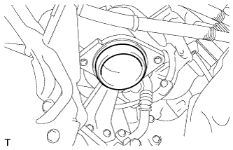
Remove the vane pump O-ring from the vane pump assembly.
-
-
REMOVE TIMING GEAR COVER INSULATOR
-
REMOVE VACUUM PUMP ASSEMBLY
-
Remove the 2 nuts, and then remove the vacuum pump and 2 O-rings.
-
-
REMOVE NO. 1 TIMING BELT COVER
-
Remove the wire harness clamp.
-
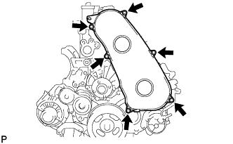
Remove the 6 bolts and timing belt cover.
-
-
REMOVE TIMING BELT
-
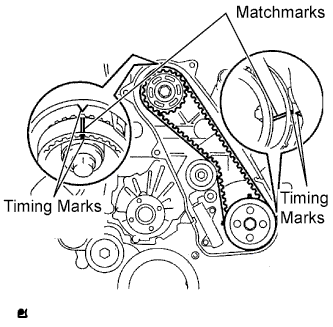
Set the No. 1 cylinder to TDC/ compression.
-
Turn the crankshaft clockwise and align the timing marks as shown in the illustration.
Tech Tips
If reusing the timing belt, draw a direction arrow on the belt (in the direction of engine revolution) and place matchmarks on the pulleys and belt as shown in the illustration.
-
-
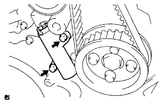
Alternately loosen the 2 bolts, and remove the timing belt tensioner.
-

Remove the timing belt.
Tech Tips
-
When turning the camshaft with the timing belt removed, first turn the crankshaft 90° counterclockwise to lower the piston.
-
When installing the timing belt, first return the camshaft to the timing marks and then turn the crankshaft clockwise until it aligns with the timing marks.
-
-
-
REMOVE NO. 1 TIMING BELT IDLER SUB-ASSEMBLY
-
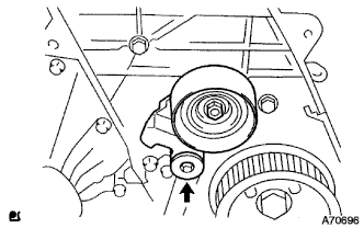
Using a 10 mm socket hexagonal wrench, remove the bolt, plate washer and timing belt idler No.1.
-
-
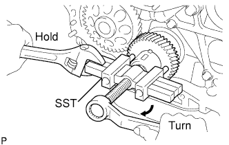
REMOVE CAMSHAFT TIMING PULLEY
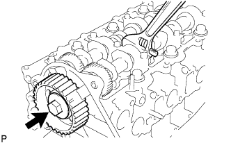
-
Remove the bolt from the camshaft timing pulley while holding the camshaft with a wrench.
-
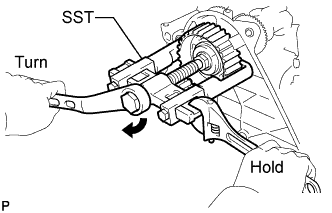
Using SST, remove the camshaft timing pulley and set key.
- SST
- 09950-40011 ( 09951-04010, 09952-04010, 09953-05010, 09957-04010 )
- 09955-04150
-
Rotate the crankshaft approximately 90° counterclockwise from the TDC position to lower the piston.
-
-
REMOVE NO. 2 TIMING BELT COVER
-
Remove the nut, 4 bolts and No. 2 timing belt cover.
-
-
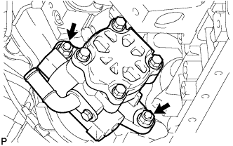
REMOVE WATER PUMP ASSEMBLY
-
Remove the 5 bolts, 2 nuts and water pump assembly.
-
-
REMOVE CRANKSHAFT POSITION SENSOR
-
Disconnect the crankshaft position sensor connector.
-
Separate the connector from the No. 1 vacuum pipe .
-
Separate the 3 wire harness clamps.
-
Remove the bolt and the crankshaft position sensor.
-
-
REMOVE CAMSHAFT POSITION SENSOR
-
Disconnect the camshaft position sensor connector.
-
Remove the bolt and the camshaft position sensor.
-
-
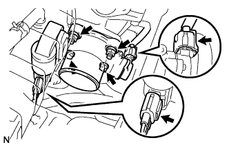
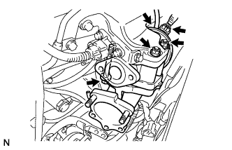
REMOVE DIESEL THROTTLE BODY ASSEMBLY
-
Disconnect the 2 throttle body connectors.
-
Remove the 2 bolts, 2 nuts, and the diesel throttle body assembly.
-
Remove the gasket from the intake air connector.
-
-
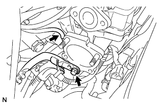
REMOVE EGR COOLER ASSEMBLY
-
Loosen the clip and disconnect the No. 4 water by-pass hose.
-
Loosen the clip and disconnect the No. 2 water by-pass hose.
-
Remove the 3 bolts and 2 nuts and remove the EGR cooler assembly.
-
-
REMOVE ELECTRIC EGR CONTROL VALVE ASSEMBLY
-
Disconnect the intake air temperature sensor connector.
-
Remove the vacuum regulating valve.
-
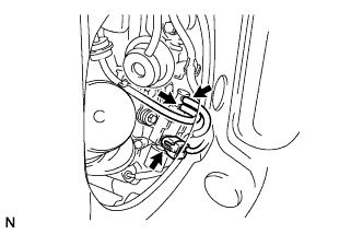
Remove the 2 vacuum hoses and the vacuum regulating valve connector.
-
Remove the 2 bolts and the vacuum regulating valve.
-
-
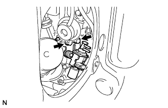
Remove the electric EGR control valve with the sensor.
-
Remove the bolt, and separate the manifold stay.
-
Disconnect the vacuum hose from the intake air connector.
-
Disconnect the EGR valve position sensor connector.
-
Disconnect the vacuum hose from the electric EGR control valve.
-
Remove the bolt, 2 nuts and intake air connector assembly.
-
Remove the 2 gaskets and electric EGR control valve from the intake air connector.
-
-
-
REMOVE MANIFOLD STAY
-
Remove the bolt and manifold stay.
-
-
REMOVE OIL LEVEL GAUGE GUIDE
-
Remove the oil level gauge.
-
Remove the bolt and oil level gauge guide.
-
-
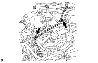
REMOVE FUEL INJECTION PIPE
-
Disconnect the fuel injector connector and harness clamps.
-
Remove the 3 bolts.
-
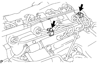
Remove the 2 bolts and remove the 2 No. 2 injection pipe clamps.
-
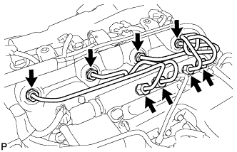
Using SST, remove the 4 injection pipes.
- SST
- 09023-12701
-
-
REMOVE FUEL INLET PIPE SUB-ASSEMBLY
-
Remove the 2 clamp bolts.
-
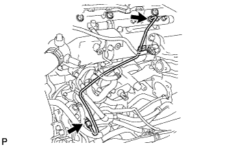
Using SST, loosen the 2 union nuts and remove the fuel inlet pipe sub-assembly.
- SST
- 09023-12701
-
-
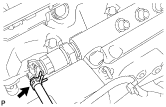
REMOVE COMMON RAIL ASSEMBLY
-
Disconnect the 2 connectors from the common rail.
-
Disconnect the fuel hose.
-
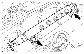
Remove the 2 bolts and remove the common rail.
-
-
REMOVE NO. 2 CAMSHAFT TIMING PULLEY FLANGE
-
Remove the 4 bolts and the No. 2 camshaft timing pulley flange.
-
-
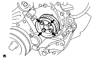
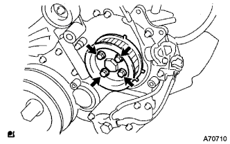
REMOVE PUMP DRIVE SHAFT PULLEY
-
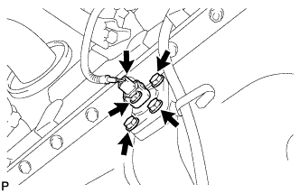
REMOVE INJECTION OR SUPPLY PUMP ASSEMBLY
-
Remove the 4 bolts.
-
Remove the No. 2 camshaft timing pulley flange and pump drive shaft pulley.
-
Using SST, remove the supply pump gear set nut and O-ring while holding the crankshaft pulley.
- SST
- 09213-58013
- 09330-00021
-
Disconnect the 2 fuel hoses.
-
Disconnect the 2 connectors and wire harness.
-
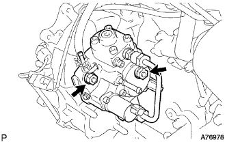
Loosen the 2 nuts as shown in the illustration.
-
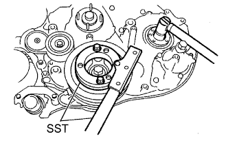
Using SST, disengage the fuel supply pump from the supply pump gear.
- SST
- 09950-50013 ( 09951-05010, 09952-05010, 09953-05020, 09954-05021 )
-
Remove the 2 nuts and fuel supply pump from the engine.
-
Remove the O-ring from the fuel supply pump.
-
Remove the pulley key from the fuel supply pump.
-
-
REMOVE CRANKSHAFT PULLEY
-
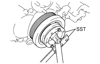
Using SST, remove the pulley bolt.
- SST
- 09213-58013
- 09330-00021
-
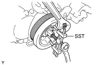
Using SST, remove the crankshaft pulley.
- SST
- 09950-50013 ( 09951-05010, 09952-05010, 09953-05020, 09954-05021 )
Note
Apply oil or grease to the threads and tip of SST (center bolt) before using it.
-
-
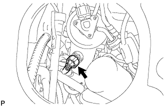
REMOVE ENGINE OIL LEVEL SENSOR
-
Disconnect the engine oil level sensor connector.
-
Remove the 4 bolts and engine oil level sensor from the oil pan.
-
Remove the gasket from the engine oil level sensor.
-
-
REMOVE OIL PAN SUB-ASSEMBLY
-
Disconnect the vinyl tubes from the oil pan.
-
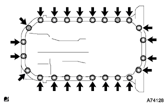
Remove the 22 bolts and 2 nuts.
-
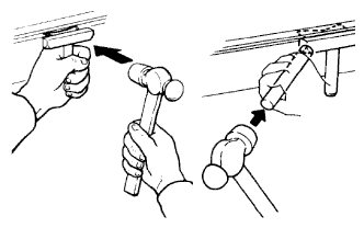
Insert the blade of a oil pan seal cutter between the oil pan and cylinder block, cut through the applied sealer and remove the oil pan.
Note
-
Do not use a oil pan seal cutter for the timing gear case side and rear oil seal retainer.
-
Be careful not to damage the oil pan flange.
-
-
-
REMOVE OIL STRAINER SUB-ASSEMBLY
-
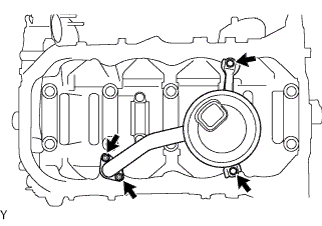
Remove the 2 nuts and 2 bolts, and then remove the oil strainer and gasket.
-
-
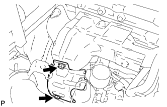
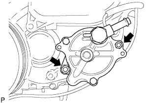
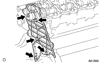
REMOVE TIMING GEAR CASE
-
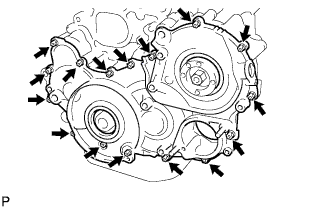
Remove the 14 bolts and 2 nuts.
-
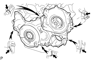
Pry the timing gear case at the locations shown in the illustration and remove the timing gear case.
Note
Do not damage the contact surface.
-
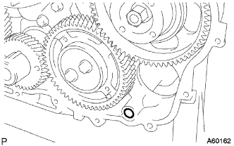
Remove the O-ring.
-
Secure the idle sub gears to the No. 1 idle gear with a service bolt.
-
-
REMOVE TIMING CHAIN OR BELT COVER OIL SEAL
-
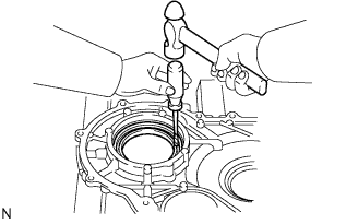
Using a screwdriver and hammer, tap out the oil seal.
-
-
REMOVE TIMING GEAR CASE OR TIMING CHAIN CASE OIL SEAL
-
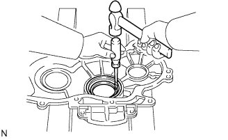
Using a screwdriver and hammer, tap out the oil seal.
-
-
REMOVE NO. 1 CRANKSHAFT POSITION SENSOR PLATE
-
Remove the No. 1 crankshaft position sensor plate.
-
-
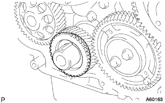
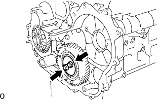
REMOVE INJECTION GEAR
-
Remove the injection gear.
-
-
REMOVE CRANKSHAFT TIMING GEAR
-
Using SST, remove the crankshaft timing gear.
- SST
- 09950-50013 ( 09951-05010, 09952-05010, 09953-05010, 09954-05011 )
-
-
REMOVE IDLE GEAR THRUST PLATE
-
Remove the 2 bolts and idle gear thrust plate.
-
-
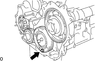
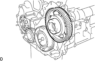
REMOVE IDLE GEAR
-
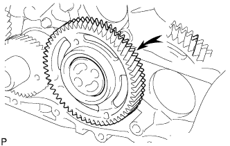
Remove the idle gear from the No. 1 idle gear shaft.
Note
Make sure that the idle sub gear and idle gear are correctly fitted to each other.
-
-
REMOVE NO. 1 IDLE GEAR SHAFT
-
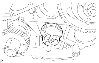
Remove the No. 1 idle gear shaft.
-
-
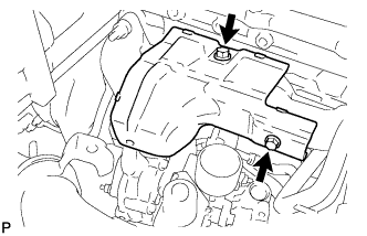
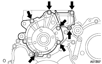
REMOVE TIMING GEAR CASE ASSEMBLY
-
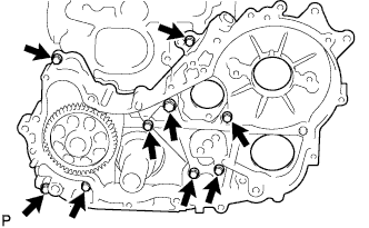
Remove the union bolt and 8 bolts.
-
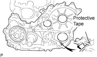
Pry the timing gear case at the locations shown in the illustration and remove the timing gear case.
Note
Do not drop the driven rotor.
-
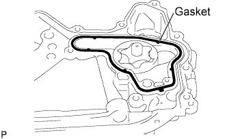
Remove the gasket from the timing gear case.
-
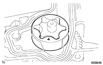
Remove the driven rotor from the timing gear case.
-
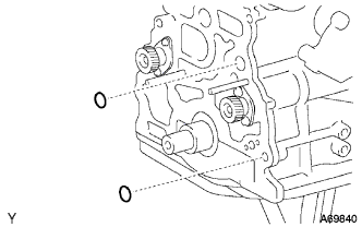
Remove the 2 O-rings from the cylinder block.
-