RADIATOR INSTALLATION

-
INSTALL RADIATOR ASSEMBLY
-
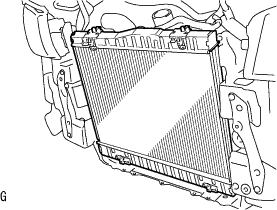
Install the radiator assembly to the vehicle.
Note
Do not drop the radiator assembly.
-
-
INSTALL FAN SHROUD NO.2
-
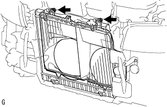
Install the fan shroud No.2 with the 2 bolts.
- Torque:
- 7.0 N*m { 71 kgf*cm, 62 in.*lbf }
Note
Do not drop the radiator assembly.
-
-
INSTALL FAN SHROUD
-
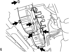
Install the fan shroud with the 6 bolts.
- Torque:
- 5.4 N*m { 53 kgf*cm, 48 in.*lbf }
Note
Do not drop the radiator assembly.
-
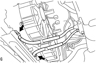
Connect the 2 reserve tank hoses.
-
Connect the 4 radiator hoses.
-
-
CONNECT OIL TUBE (for Automatic Transmission)
-
Connect the 2 oil tubes to the radiator assembly.
-
-
INSTALL COOLING FAN ECU
-
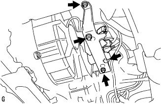
Install the cooling fan ECU with the 2 bolts and 2 nuts.
- Torque:
- 20 N*m { 204 kgf*cm, 15 ft.*lbf }
-
-
INSTALL RADIATOR SUPPORT UPPER
-
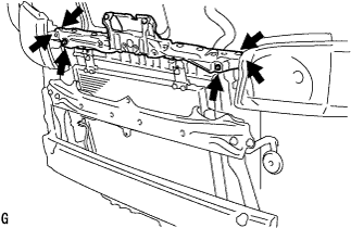
Install the radiator support upper with the 6 bolts.
- Torque:
- 5.5 N*m { 56 kgf*cm, 49 in.*lbf }
-
-
INSTALL WINDSHIELD WASHER MOTOR AND PUMP ASSEMBLY
-
Install the windshield washer motor and pump assembly with the 2 bolts.
- Torque:
- 7.0 N*m { 71 kgf*cm, 62 in.*lbf }
-
-
INSTALL RADIATOR RESERVE TANK ASSEMBLY
-
Install the radiator reserve tank assembly with the bolt.
- Torque:
- 7.0 N*m { 71 kgf*cm, 62 in.*lbf }
-
-
AIRTIGHT CHECK
-
Apply some soapy water to the junction of the radiator tank lower, radiator tank upper and radiator core.
-
Remove the radiator reservoir cap.
-
Attach the radiator cap tester.
-
Check if the radiator assembly is airtight by pumping the radiator cap tester.
-
-
INSTALL INTERCOOLER ASSEMBLY
-
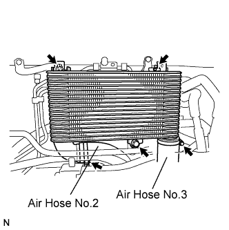
Temporarily install the intercooler assembly with the 3 bolts.
-
Connect the air hose No.2, and tighten the clamp.
-
Connect the air hose No.3, and tighten the clamp.
-
Tighten the intercooler assembly.
- Torque:
- 18 N*m { 180 kgf*cm, 13 ft.*lbf }
- 6.0 N*m { 61 kgf*cm, 53 in.*lbf }
-
-
INSTALL HOOD LOCK ASSEMBLY
-
Install the hood lock cable assembly to the hood lock assembly.
-
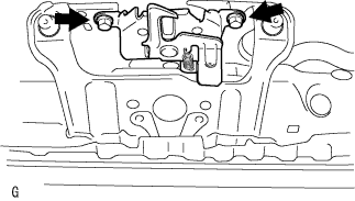
Install the hood lock assembly with the 2 bolts.
- Torque:
- 12 N*m { 122 kgf*cm, 9 ft.*lbf }
-
-
INSTALL W/RECEIVER CONDENSER ASSEMBLY (w/ Air Conditioning System)
-
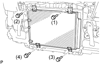
Install the w/ receiver condenser assembly with the 4 bolts.
Note
Tighten in the order indicated in the illustration.
Tech Tips
If the condenser is replaced with a new one, add compressor oil to the new condenser.
Capacity 40 cc (1.4fl.oz.) Compressor oil ND-OIL 8 or equivalent
-
-
INSTALL COOLER REFRIGERANT LIQUID PIPE A (w/ Air Conditioning System)
-
Remove the attached vinyl tape from the pipe and the connecting part of the cooler condenser assembly.
-
Sufficiently apply compressor oil to a new O-ring and the fitting surface of the pipe joint.
Compressor oil ND-OIL 8 or equivalent -
Install the O-ring on the cooler refrigerant liquid pipe A.
-
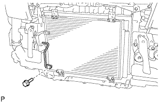
Install the cooler refrigerant liquid pipe A on the cooler condenser assembly with the bolt.
- Torque:
- 5.4 N*m { 55 kgf*cm, 47 in.*lbf }
-
Install the clamp with the bolt.
-
-
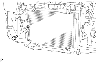
INSTALL COOLER REFRIGERANT DISCHARGE PIPE A (w/ Air Conditioning System)
-
Remove the attached vinyl tape from the pipe and the connecting part of the cooler condenser assembly.
-
Sufficiently apply compressor oil to a new O-ring and the fitting surface of the pipe joint.
Compressor oil ND-OIL 8 or equivalent -
Install the O-ring on the cooler refrigerant discharge pipe A.
-
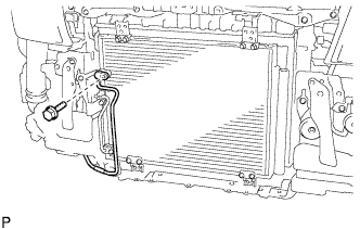
Install the cooler refrigerant discharge pipe A on the cooler condenser assembly with the bolt.
- Torque:
- 5.4 N*m { 55 kgf*cm, 47 in.*lbf }
-
-
INSTALL FRONT BUMPER REINFORCEMENT
-
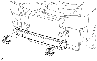
Install the front bumper reinforcement with the 6 bolts.
- Torque:
- 61 N*m { 622 kgf*cm, 45 ft.*lbf }
-
-
INSTALL FRONT FLOOR CROSS MEMBER REINFORCEMENT SUB-ASSEMBLY RH
-
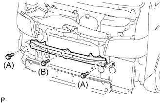
Install the front floor cross member reinforcement sub-assembly with the 5bolts.
- Torque:
- BOLT A
- 61 N*m { 622 kgf*cm, 45 ft.*lbf }
- BOLT B
- 12 N*m { 122 kgf*cm, 9 ft.*lbf }
-
-
INSTALL HOOD LOCK SUPPORT BRACE SUB-ASSEMBLY
-
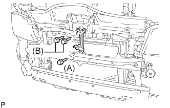
Install the hood lock support brace sub-assembly with the 3 bolts.
- Torque:
- BOLT A
- 12 N*m { 122 kgf*cm, 9 ft.*lbf }
- BOLT B
- 5.5 N*m { 56 kgf*cm, 49 in.*lbf }
-
-
INSTALL AIR INLET DUCT NO.1
-
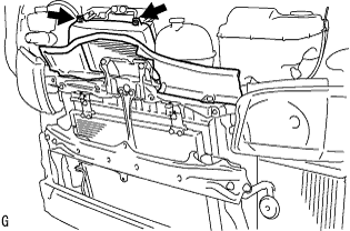
Install the air inlet duct No.1 and air inlet duct No.2 with the 7clamps and 2 bolts.
-
-
INSTALL FRONT BUMPER
-
INSTALL STEP PLATE COVER RH
-
INSTALL STEP PLATE COVER LH
-
INSTALL RADIATOR GRILLE
-
ADD ENGINE COOLANT
-
Firmly tighten the drain plugs and fill the radiator reserve tank assembly with coolant to the top of the inlet.
-
Loosen the bleeder plug of outlet housing.
-
When air is bled and the coolant drains out, firmly install the bleeder plug.
-
Add coolant up to the B line mark in the radiator reserve tank assembly and install the radiator cap.
Coolant capacity Condition Capacity w/ rear heater 17.0 liters (18.0 US qts, 15.0 imp. qts) w/o rear heater 15.0 liters (15.9 US qts, 13.2 imp. qts) -
Warm up the engine.
-
After the engine cools down check that the coolant level is between the LOW and FULL level marks.
-
-
CHARGE REFRIGERANT (w/ Air Conditioning System)
-
Perform vacuum purging using a vacuum pump.
-
Charge with refrigerant HFC-134a (R134a).
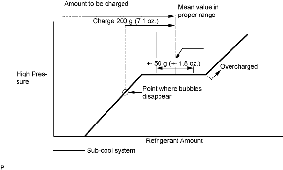
Standard Single A/C 520 to 580g (18.3 to 20.5 oz.) Dual A/C 670 to 730g (23.0 to 25.7 oz.) - SST
- 07110-58060 ( 07117-58090, 07117-78050, 07117-58070, 07117-58060, 07117-58080, 07117-88060, 07117-88070, 07117-88080 )
Note
-
Do not operate the cooler compressor before charging refrigerant as the cooler compressor does not work properly without any refrigerant, which causes the compressor to overheat.
-
Approximately 100 g (3.5 oz.) of refrigerant may need to be charged after bubbles disappear. The refrigerant amount should be checked by quantity, and not with the sight glass.
Tech Tips
Prepare a service can to recharge refrigerant if using the refrigerant gas collected with the freon collection/recycling device because the collective rate of the device is approximately 90%.
-
-
WARM UP ENGINE
-
Warm up the engine at less than 1,850 rpm for 2 minutes or more after charging refrigerant.
Note
Be sure to warm up the compressor when turning the A/C switch on after removing and installing the cooler refrigerant lines (including the compressor), to prevent damage to the compressor.
-
-
CHECK FOR ENGINE COOLANT LEAKS
CAUTION:
Do not remove the radiator cap while the engine and radiator are still hot. Pressurized, hot engine coolant and steam may be released and cause serious burns.
-
Fill the radiator with coolant and attach a radiator cap tester to the radiator.
-
Warm up the engine.
-
Using a radiator cap tester, increase the pressure inside the radiator to 137 kPa (1.4 kgf/cm2, 19.9 psi), and check that the pressure does not drop.
Tech Tips
If the pressure drops, check the hoses, radiator or water pump for leaks. If no external leaks are found, check the heater core, cylinder block and cylinder head.
-
-
CHECK FOR LEAKAGE OF REFRIGERANT (w/ Air Conditioning System)
-
After recharging refrigerant gas, check for leakage of refrigerant gas using a halogen leak detector.
-
Carry out the test under the following conditions:
-
Stop the engine.
-
Secure good ventilation (the gas leak detector may react to volatile gases which are not refrigerant, such as evaporated gasoline and exhaust gas).
-
Repeat the test 2 or 3 times.
-
Make sure that there is some refrigerant remaining in the refrigeration system.
When the compressor is off: approx. 392 to 588 kPa (4 to 6 kgf/cm2, 57 to 85 psi)
-
-
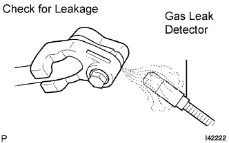
Using a gas leak detector, check for leakage of the refrigerant line.
-
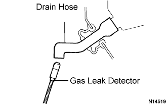
Bring the gas leak detector close to the drain hose with the detector's power off.
Tech Tips
-
After the blower motor has stopped, let the cooling unit stand for more than 15 minutes.
-
Bring the gas leak detector sensor under the drain hose.
-
When bringing the gas leak detector close to the drain hose, make sure that the gas leak detector does not react to volatile gases.
If such reaction is unavoidable, the vehicle must be lifted up.
-
-
If a gas leak is not detected on the drain hose, remove the blower motor control from the cooling unit. Insert the gas leak detector sensor into the unit and perform the test.
-
Disconnect the pressure switch connector and leave it for approximately 20 minutes. Bring the gas leak detector close to the pressure switch and perform the test.
-