THERMOSTAT INSTALLATION

-
INSTALL THERMOSTAT
-
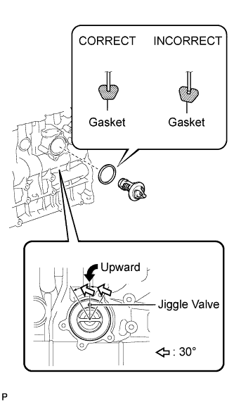
Install a new gasket onto the thermostat.
Tech Tips
When installing the thermostat onto the gasket, be careful not to deform the gasket. Make sure that the thermostat is properly installed into the groove of the gasket, as shown in the illustration.
-
Insert the thermostat into the cylinder block with the jiggle valve facing straight upward.
Tech Tips
The jiggle valve may be set within 30° on either side of the prescribed position.
-
-
INSTALL WATER INLET
-
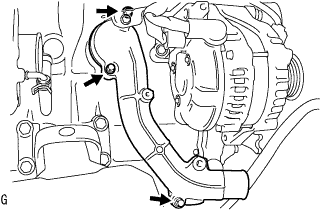
Install the water inlet with the 3 bolts.
- Torque:
- 13 N*m { 133 kgf*cm, 10 ft.*lbf }
-
-
CONNECT NO. 4 RADIATOR HOSE
-
INSTALL COMPRESSOR OUTLET ELBOW
-
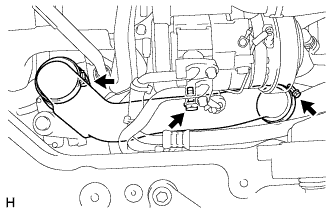
Install the compressor outlet elbow with the 2 hose clamps and bolt.
- Torque:
- 12 N*m { 122 kgf*cm, 9 ft.*lbf }
-
-
INSTALL NO. 1 AIR CLEANER HOSE
-
Install the air cleaner hose to the compressor inlet elbow.
Note
Pull the hose to make sure that it is locked and securely connected.
-
-
INSTALL AIR TUBE ASSEMBLY
-
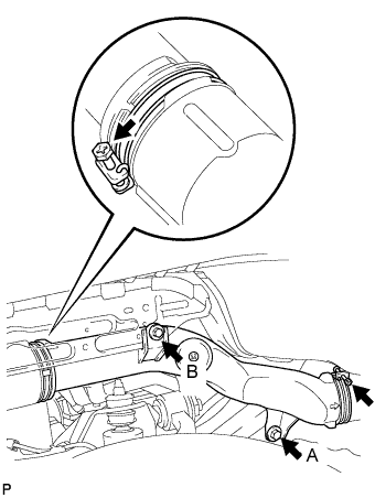
Install the air tube assembly with the 2 hose clamps and 2 bolts.
- Torque:
- 18 N*m { 180 kgf*cm, 13 ft.*lbf, for bolt A }
- 7.0 N*m { 71 kgf*cm, 62 in.*lbf, for bolt B }
-
-
INSTALL W/ PULLEY COMPRESSOR ASSEMBLY (w/ Air Conditioning System)
-
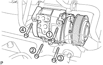
Install the compressor and magnetic clutch with the 4 bolts.
- Torque:
- 25 N*m { 255 kgf*cm, 18 ft.*lbf }
Note
Tighten the bolts in the order shown in the illustration to install the compressor and magnetic clutch.
-
-
INSTALL FAN & GENERATOR V BELT (w/ Air Conditioning System)
-
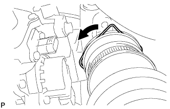
Rotate the V-ribbed belt tensioner pulley clockwise, and then install the fan and generator V belt.
Note
Make sure that the fan and generator V belt is set properly on each pulley.
-
Check that the indicator mark of the V-ribbed belt tensioner Click here.
-
-
CONNECT CABLE TO NEGATIVE BATTERY TERMINAL
- Torque:
- 5.4 N*m { 55 kgf*cm, 48 in.*lbf }
-
ADD ENGINE COOLANT
-
Firmly tighten the drain plugs.
-
Fill the radiator reserve tank assembly with coolant to the top of the inlet.
Coolant capacity Condition Capacity w/ rear heater 18.2 liters (19.2 US qts, 16.0 lmp. qts) w/o rear heater 16.2 liters (17.0 US qts, 14.0 lmp. qts) Note
Do not substitute plain water for engine coolant.
Tech Tips
-
Use of improper coolants may damage the engine cooling system.
-
Use only Toyota Super Long Life Coolant or similar high quality ethylene glycol based non-silicate, non-amine, non-nitrite, and non-borate coolant with long-life hybrid organic acid technology (coolant with long-life hybrid organic acid technology consists of a combination of low phosphates and organic acids).
-
-
Loosen the bleeder plug of the outlet housing.
-
When air is bled and the coolant drains out, firmly install the bleeder plug.
-

Add coolant up to the B line mark in the radiator reserve tank assembly and install the radiator cap.
-
Warm up the engine until the thermostat opens.
-
While the thermostat is open, circulate the coolant for several minutes.
Tech Tips
The thermostat open timing can be confirmed by pressing the inlet radiator hose by hand, and checking when the engine coolant starts to flow inside the hose.
-
-

After the engine cools down, check that the coolant level is between the LOW and FULL level marks.
-
-
INSPECT FOR COOLANT LEAK
CAUTION:
Do not remove the radiator cap while the engine and radiator are still hot. Hot, pressurized engine coolant and steam may be released and cause serious burns.
-
Fill the radiator with coolant and attach a radiator cap tester to the radiator.
-
Warm up the engine.
-
Using a radiator cap tester, increase the pressure inside the radiator to 137 kPa (1.4 kgf/cm2, 19.9 psi), and check that the pressure does not drop.
Tech Tips
If the pressure drops, check the hoses, radiator and water pump for leaks. If no external leaks are found, check the heater core, cylinder block and cylinder head.
-
-
INSTALL FENDER APRON MUDGUARD SEAL RH
-
Install the fender apron mudguard seal with the 4 clips.
-
-
INSTALL ENGINE SERVICE HOLE SUB COVER SUB-ASSEMBLY
-
Install the engine service hole sub cover with the 5 bolts.
- Torque:
- 13 N*m { 133 kgf*cm, 10 ft.*lbf }
-
-
INSTALL FRONT SEAT ASSEMBLY RH
-

Connect the front seat inner belt assembly connector and install the front seat assembly.
-
Align the front seat assembly adjuster pin with the holes in the body.
-
Move the front seat assembly to the rearmost position.
Note
Make sure that the front seat assembly is securely locked.
-
Temporarily tighten the 2 bolts on the front side of the front seat assembly.
-
Move the front seat assembly fully forward.
Note
Make sure that the front seat assembly is securely locked.
-
Temporarily tighten the 2 bolts on the rear side of the front seat assembly.
-
Move the front seat assembly to the rearmost position.
Note
Make sure that the front seat assembly is securely locked.
-
Fully tighten the 2 bolts on the front side of the front seat assembly in the order of outer and inner side.
- Torque:
- 39 N*m { 398 kgf*cm, 29 ft.*lbf }
-
Move the front seat assembly fully forward.
Note
Make sure that the front seat assembly is securely locked.
-
Fully tighten the 2 bolts on the rear side of the front seat assembly in the order of outer and inner side.
- Torque:
- 39 N*m { 398 kgf*cm, 29 ft.*lbf }
-
-
INSTALL FRONT DOOR SCUFF PLATE RH