WATER PUMP REMOVAL

-
DISCONNECT CABLE FROM NEGATIVE BATTERY TERMINAL
-
REMOVE FRONT DOOR SCUFF PLATE RH
-
REMOVE FRONT SEAT ASSEMBLY RH
-

Move the front seat assembly fully forward.
-
Remove the 2 bolts on the rear side of the seat.
-
Move the front seat assembly to the rearmost position.
-
Remove the 2 bolts on the front side of the seat.
-
Move the front seat assembly to the center of the seat slide rail. Set the seatback in the upright position.
-
Disconnect the front seat inner belt assembly connector.
-
Remove the front seat assembly.
-
-
REMOVE ENGINE SERVICE HOLE SUB COVER SUB-ASSEMBLY
-
Roll up the carpet, and remove the 5 bolts and engine service hole sub cover sub-assembly.
-
-
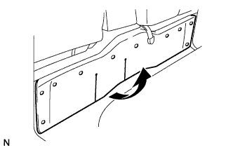
REMOVE NO. 2 ENGINE SERVICE HOLE COVER
-
Roll up the carpet.
-
Remove the 3 bolts and No. 2 engine service hole cover.
-
-
REMOVE RADIATOR HOSE INLET
-
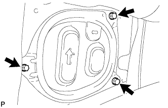
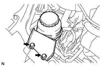
SEPARATE VANE PUMP OIL RESERVOIR ASSEMBLY
-
Remove the 2 bolts, and separate the vane pump oil reservoir assembly.
-
-
LOOSEN FAN PULLEY
-
Loosen the 4 nuts from the fan pulley.
-
-
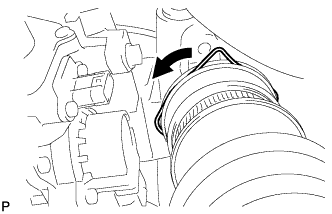
REMOVE FAN & GENERATOR V BELT
-
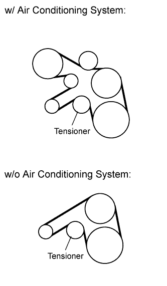
Remove the drive belt by rotating the tensioner pulley clockwise to loosen its tension with the pulley set bolt of the tensioner.
-
-
REMOVE FAN PULLEY
-
Remove the 4 nuts and fan pulley.
-
-
REMOVE FENDER APRON MUDGUARD SEAL RH
-
Disengage the 3 clips and remove the fender apron mudguard seal RH.
-
-
SEPARATE W/ PULLEY COMPRESSOR ASSEMBLY (w/ Air Conditioning System)
-
Disconnect the connector.
-
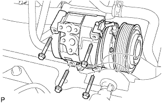
Remove the 4 bolts and compressor and magnetic clutch.
-
-
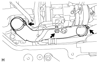
REMOVE AIR TUBE ASSEMBLY
-
Loosen the 2 hose clamps.
-
Remove the 2 bolts and air tube.
-
-
REMOVE NO. 1 AIR CLEANER HOSE
-
Pull the stopper upward and disconnect the No. 1 air cleaner hose from the compressor inlet elbow.
-
-
REMOVE COMPRESSOR OUTLET ELBOW
-
Remove the 2 hose clamps, bolt and compressor outlet elbow.
-
-
REMOVE COMPRESSOR MOUNTING BRACKET NO.1 (w/ Air Conditioning System)
-
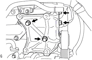
Remove the 4 bolts and compressor bracket.
-
-
REMOVE NO. 2 IDLE PULLEY ASSEMBLY (w/ Air Conditioning System)
-
Remove the bolt, washers and idle pulley assembly.
-
-
REMOVE GENERATOR BRACKET
-
Remove the 2 bolts, then remove the generator bracket.
-
-
REMOVE GENERATOR ASSEMBLY
-
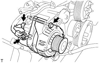
Disconnect the generator connector.
-
Remove the terminal cap.
-
Remove the nut and disconnect the wire harness from terminal B.
-
Remove the bolt and generator.
-
-
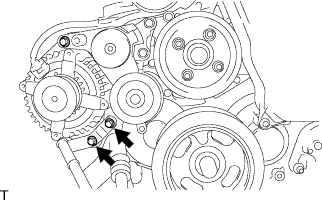
REMOVE V-RIBBED BELT TENSIONER ASSEMBLY
-
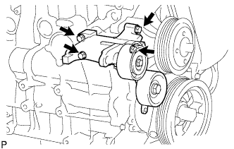
Remove the 4 bolts and belt tensioner assembly.
-
-
REMOVE NO. 1 TIMING BELT COVER
-
Remove the wire harness clamp.
-
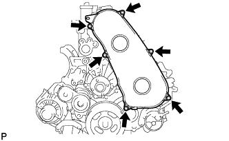
Remove the 6 bolts and timing belt cover.
-
-
REMOVE TIMING BELT
-
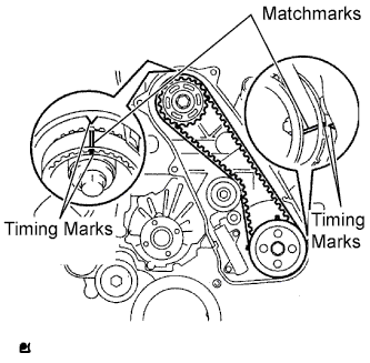
Set the No. 1 cylinder to TDC/ compression.
-
Turn the crankshaft clockwise and align the timing marks as shown in the illustration.
Tech Tips
If reusing the timing belt, draw a direction arrow on the belt (in the direction of engine revolution) and place matchmarks on the pulleys and belt as shown in the illustration.
-
-
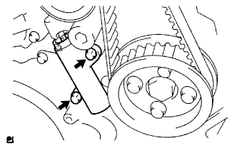
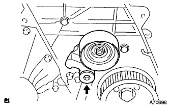
Alternately loosen the 2 bolts, and remove the timing belt tensioner.
-

Remove the timing belt.
Tech Tips
-
When turning the camshaft with the timing belt removed, first turn the crankshaft 90° counterclockwise to lower the piston.
-
When installing the timing belt, first return the camshaft to the timing marks and then turn the crankshaft clockwise until it aligns with the timing marks.
-
-
-
REMOVE OIL LEVEL GAUGE GUIDE
-
Remove the oil level gauge.
-
Remove the bolt and oil level gauge guide.
-
-
REMOVE INJECTION PIPE
-
Disconnect the fuel injector connector and harness clamps.
-
Remove the 3 bolts.
-
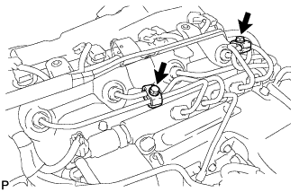
Remove the 2 bolts and remove the 2 No. 2 injection pipe clamps.
-
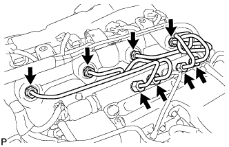
Using SST, remove the 4 injection pipes.
- SST
- 09023-12701
-
-
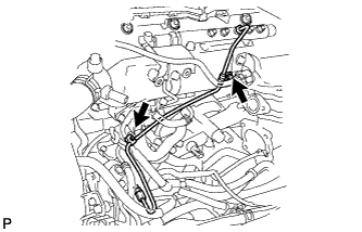
REMOVE FUEL INLET PIPE SUB-ASSEMBLY
-
Remove the 2 clamp bolts.
-
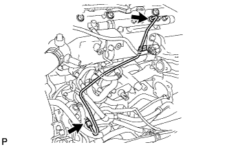
Using SST, loosen the 2 union nuts and remove the fuel inlet pipe sub-assembly.
- SST
- 09023-12701
-
-
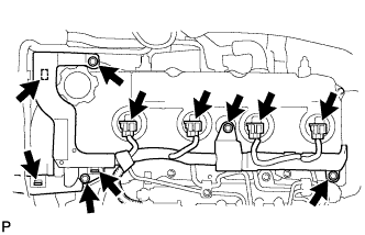
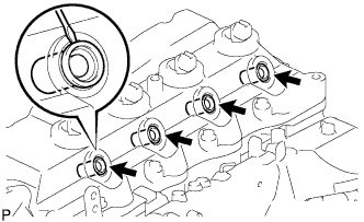
REMOVE CYLINDER HEAD COVER SUB-ASSEMBLY
-
Using a small screwdriver, remove the 4 holder seals by prying the portion between the holder seal and the cutout part of the cylinder head.
-
Disconnect the ventilation hose.
-
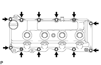
Remove the 10 bolts, 2 nuts, cylinder head cover and the cylinder head cover gasket.
-
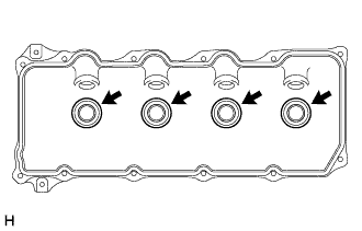
Remove the 4 No. 3 cylinder head cover gaskets from the cylinder head cover.
-
-
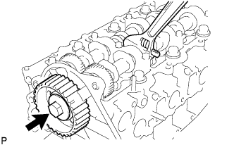
REMOVE CAMSHAFT TIMING PULLEY
-
Remove the bolt from the camshaft timing pulley while holding the camshaft with a wrench.
-
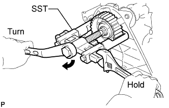
Using SST, remove the camshaft timing pulley and set key.
- SST
- 09950-40011 ( 09951-04010, 09952-04010, 09953-05010, 09957-04010 )
- 09955-04150
-
Rotate the crankshaft approximately 90° counterclockwise from the TDC position to lower the piston.
-
-
REMOVE NO. 1 TIMING BELT IDLER SUB-ASSEMBLY
-
Using a 10 mm socket hexagonal wrench, remove the bolt, plate washer and timing belt idler No.1.
-
-
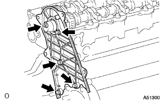
REMOVE NO. 2 TIMING BELT COVER
-
Remove the nut, 4 bolts and No. 2 timing belt cover.
-
-
REMOVE WATER PUMP ASSEMBLY
-
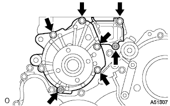
Remove the 5 bolts, 2 nuts and water pump assembly.
-