EXHAUST PIPE INSTALLATION

-
INSTALL EXHAUST TAIL PIPE ASSEMBLY
-
Connect the 4 No. 4 exhaust pipe supports to install the exhaust tail pipe assembly.
-
-
INSTALL FRONT EXHAUST PIPE ASSEMBLY
-
Inspect the compression spring.
-
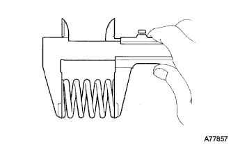
Using vernier calipers, measure the free length of the compression springs.
Minimum length 40.5 mm (1.59 in.) Tech Tips
If the free length is less than the minimum, replace the compression spring.
-
-
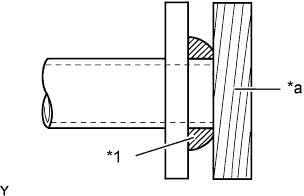
Text in Illustration *1 Gasket *a Wooden Block Install the gasket.
-
Fully insert 2 new gaskets to the exhaust manifold and front exhaust pipe assembly by hand.
-
Using a wooden block, uniformly strike the gasket so that the gasket and exhaust manifold and front exhaust pipe assembly are properly fit.
Note
-
Be careful with the installation direction of the gasket.
-
Do not reuse the gasket.
-
Do not damage the gasket.
-
To ensure a proper seal, do not use the front exhaust pipe assembly to force the gasket onto the exhaust manifold.
-
To ensure a proper seal, do not use the tail exhaust pipe assembly to force the gasket onto the front exhaust pipe assembly.
-
-
-
Connect the No. 4 exhaust pipe support to install the front exhaust pipe assembly.
-
Temporarily install the 4 compression springs and 4 bolts to the front exhaust pipe assembly.
-
Tighten the 4 bolts.
- Torque:
- 43 N*m { 438 kgf*cm, 32 ft.*lbf }
Note
After installation, check that the clearance is almost the same at any point between the flanges of the exhaust manifold, tail exhaust pipe assembly and front exhaust pipe assembly.
-
-
INSTALL OXYGEN SENSOR
-
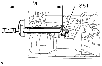
Text in Illustration *a Fulcrum Length Using SST, install the heated oxygen sensor to the front exhaust pipe assembly.
- SST
- 09224-00010
- Torque:
- without SST
- 44 N*m { 449 kgf*cm, 32 ft.*lbf }
- with SST
- 40 N*m { 408 kgf*cm, 30 ft.*lbf }
Tech Tips
-
Use a torque wrench with a fulcrum length of 30 cm (11.8 in.). If using a torque wrench with a length that is not 30 cm (11.8 in.), calculate the torque specification for the torque wrench and SST based on the "without SST" torque specification Click here.
-
Make sure SST and the wrench are connected in a straight line.
-
Connect the heated oxygen sensor connector.
-
-
INSTALL AIR FUEL RATIO SENSOR
-
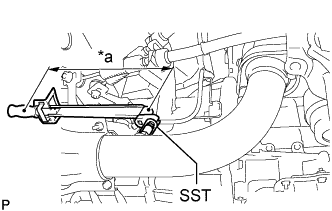
Text in Illustration *a Fulcrum Length Using SST, install the air fuel ratio sensor to the front exhaust pipe assembly.
- SST
- 09224-00010
- Torque:
- without SST
- 44 N*m { 449 kgf*cm, 32 ft.*lbf }
- with SST
- 40 N*m { 408 kgf*cm, 30 ft.*lbf }
Tech Tips
-
Use a torque wrench with a fulcrum length of 30 cm (11.8 in.). If using a torque wrench with a length that is not 30 cm (11.8 in.), calculate the torque specification for the torque wrench and SST based on the "without SST" torque specification Click here.
-
Make sure SST and the wrench are connected in a straight line.
-
Connect the air fuel ratio sensor connector.
-
-
INSPECT FOR EXHAUST GAS LEAK
If gas is leaking, tighten the areas necessary to stop the leak. Replace damaged parts as necessary.