TURBOCHARGER INSTALLATION

-
TEMPORARILY TIGHTEN TURBOCHARGER SUB-ASSEMBLY
-
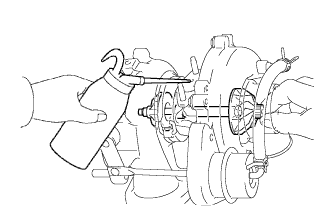
If replacing the turbocharger, add 20 cm3(1.2 cu in.) of fresh oil into the turbocharger oil inlet hole and turn the turbine wheel by hand to spread oil to the bearing.
-
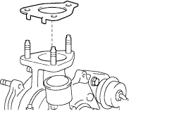
Install a new turbo to exhaust manifold gasket as shown in the illustration.
-
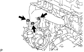
Temporarily tighten the turbocharger assembly with the 3 nuts to exhaust manifold.
-
-
TEMPORARILY TIGHTEN TURBO OIL INLET PIPE SUB-ASSEMBLY
-
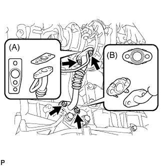
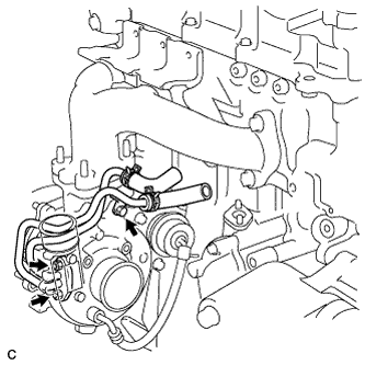
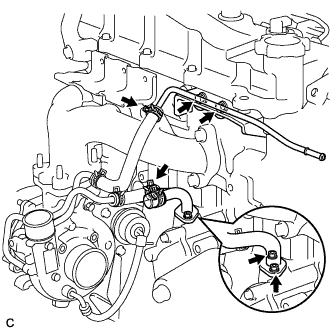
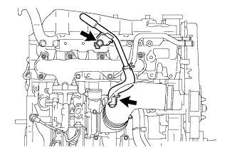
Install a new turbo oil inlet gasket (A) and an outlet gasket (B) and temporarily tighten the turbo inlet pipe with the 2 bolts and 2 nuts.
-
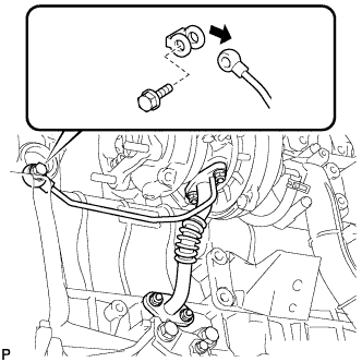
Install a new gasket and temporarily tighten the turbo inlet pipe with the union bolt.
Tech Tips
Be sure to install the turbo oil inlet pipe with the turbo charger assembly temporarily tightened so that the positions of the turbo and cylinder block can be adjusted.
-
-
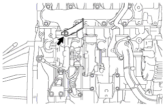
TEMPORARILY TIGHTEN TURBOCHARGER STAY
-
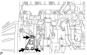
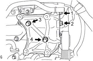
Temporarily tighten the turbocharger stay with the 3 bolts.
-
-
FULLY TIGHTEN TURBOCHARGER SUB-ASSEMBLY
-
Tighten the turbocharger with the 3 nuts to align the turbocharger and turbo oil inlet pipe.
- Torque:
- 52 N*m { 530 kgf*cm, 38 ft.*lbf }
-
Tighten the turbocharger stay.
- Torque:
- 24 N*m { 245 kgf*cm, 18 ft.*lbf }
-
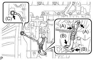
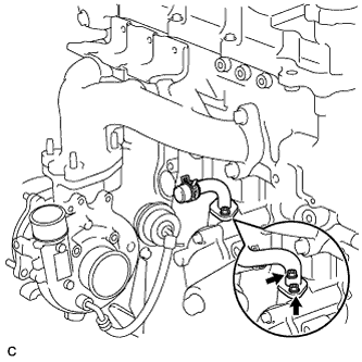
Tighten the turbo oil inlet pipe.
- Torque:
- Nut A
- 13 N*m { 133 kgf*cm, 10 ft.*lbf }
- Bolt B
- 12 N*m { 122 kgf*cm, 9 ft.*lbf }
- Bolt C
- 26 N*m { 260 kgf*cm, 19 ft.*lbf }
-
-
INSTALL TURBINE OUTLET ELBOW
-
Install a new gasket to the turbocharger.
-
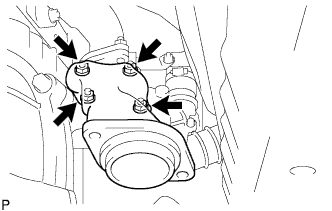
Install the turbine outlet elbow with 4 new bolts.
- Torque:
- 26 N*m { 260 kgf*cm, 19 ft.*lbf }
-
-
INSTALL EXHAUST PIPE ASSEMBLY FRONT (for Long Wheelbase)
-
Inspect the compression spring.
-
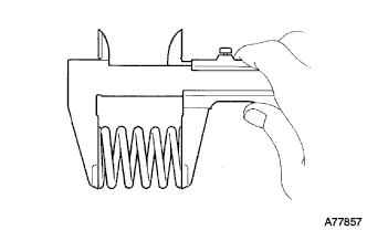
Using vernier calipers, measure the free length of the compression springs.
Minimum length 40.5mm (1.594 in.) Tech Tips
If the free length is less than the minimum, replace the compression spring.
-
-
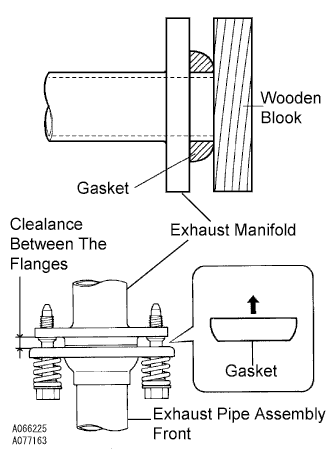
Install the gasket.
-
Fully insert a new gasket to the exhaust manifold by hand.
-
Using a wooden block, uniformly strike the gasket so that the gasket and exhaust manifold are properly fit.
Note
-
Be careful with the installation direction of the gasket.
-
Do not reuse the gasket.
-
Do not damage the gasket.
-
To ensure a proper seal, do not use the exhaust pipe assembly front to force the gasket onto the front exhaust manifold.
-
-
-
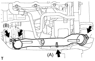
Connect the exhaust pipe support, and install the exhaust pipe assembly front with the 4 bolts, 2 compression springs and 2 nuts.
- Torque:
- exhaust manifold side
- 43 N*m { 438 kgf*cm, 32 ft.*lbf }
- exhaust pipe assembly front side
- 48 N*m { 489 kgf*cm, 35 ft.*lbf }
Note
After installation, check that the clearance is almost same at any point between the flanges of the exhaust manifold and exhaust pipe assembly front.
-
-
INSTALL EXHAUST PIPE ASSEMBLY FRONT (for Super Long Wheelbase)
-
Inspect the compression spring.
-
Using vernier calipers, measure the free length of the compression springs.
Minimum length 40.5mm(1.594 in.) Tech Tips
If the free length is less than the minimum, replace the compression spring.
-
-
Install the gasket.
-
Fully insert a new gasket to the exhaust manifold by hand.
-
Using a wooden block, uniformly strike the gasket so that the gasket and exhaust manifold are properly fit.
Note
-
Be careful with the installation direction of the gasket.
-
Do not reuse the gasket.
-
Do not damage the gasket.
-
To ensure a proper seal, do not use the exhaust pipe assembly front to force the gasket onto the front exhaust manifold.
-
-
-
Connect the exhaust pipe support, and install the exhaust pipe assembly front and a new gasket with the 4 bolts, 2 compression springs and 2nuts.
- Torque:
- Exhaust manifold side
- 43 N*m { 438 kgf*cm, 32 ft.*lbf }
- Exhaust pipe assembly center side
- 48 N*m { 489 kgf*cm, 35 ft.*lbf }
Note
After installation, check that the clearance is almost same at any point between the flanges of the exhaust manifold and exhaust pipe assembly front .
-
-
INSTALL TURBO WATER PIPE SUB-ASSEMBLY NO.2 (for Water Cooled Turbocharger)
-
Install a new gasket onto the turbocharger.
-
Install the turbo water pipe No.2 with the bolt and 2 nuts to the turbocharger.
- Torque:
- Bolt
- 12 N*m { 122 kgf*cm, 9 ft.*lbf }
- Nut
- 8.0 N*m { 82 kgf*cm, 71 in.*lbf }
-
-
INSTALL WATER BY-PASS PIPE SUB-ASSEMBLY NO.2
-
Water cooled turbocharger (w/ heater)
-
Install a new gasket onto the cylinder block.
-
Install the water by-pass pipe No.2 with the bolt and 2 nuts.
- Torque:
- Bolt
- 18 N*m { 184 kgf*cm, 13 ft.*lbf }
- Nut
- 8.0 N*m { 82 kgf*cm, 71 in.*lbf }
-
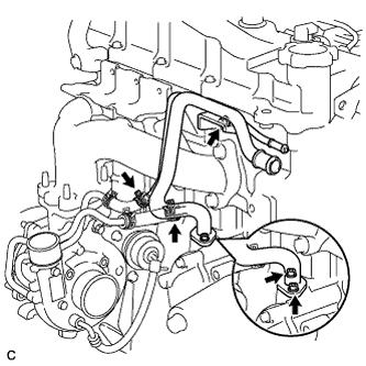
Connect the 2 water hoses with the 2 clips.
-
Connect the water by-pass hose No.3 with the clip.
-
Connect the heater water inlet hose with the clip.
-
-
Water cooled turbocharger (w/o heater)
-
Install a new gasket onto the cylinder block.
-
Install the water by-pass pipe No.2 with the 2 nuts.
- Torque:
- 8.0 N*m { 82 kgf*cm, 71 in.*lbf }
-
Install the turbo water pipe No.2 with the 2 bolts.
- Torque:
- 18 N*m { 184 kgf*cm, 13 ft.*lbf }
-
Connect the 2 water hoses with the 2 clips.
-
Connect the water by-pass hose No.3 with the clip.
-
-
Air cooled turbocharger (w/o heater)
-
Install a new gasket onto the cylinder block.
-
Install the water by-pass pipe No.2 with the 2 nuts.
- Torque:
- 8.0 N*m { 82 kgf*cm, 71 in.*lbf }
-
-
-
INSTALL COMPRESSOR ELBOW STAY
-
Install the compressor elbow stay with the bolt.
- Torque:
- 32 N*m { 326 kgf*cm, 23 ft.*lbf }
-
-
INSTALL COMPRESSOR OUTLET ELBOW
-
Install the compressor outlet elbow with the 2 bolts and 2 clamps.
- Torque:
- Bolt (A)
- 12 N*m { 122 kgf*cm, 9 ft.*lbf }
- Bolt (B)
- 32 N*m { 326 kgf*cm, 24 ft.*lbf }
-
-
INSTALL AIR CLEANER HOSE ASSEMBLY
-
Install the air cleaner hose assembly with the clamp.
-
-
INSTALL AIR TUBE ASSEMBLY
-
Install the air tube assembly with the 2 clamps and 2 bolts.
-
-
INSTALL VENTILATION PIPE
-
Install the ventilation pipe with the bolt and clip.
- Torque:
- 20 N*m { 204 kgf*cm, 15 ft.*lbf }
-
-
INSTALL COMPRESSOR BRACKET (w/ Air Conditioning)
-
Temporarily install the compressor bracket with the 4 bolts.
Tech Tips
Make sure that the compressor bracket is in contact with the engine block.
-
Install the compressor bracket by tightening the 4 bolts as shown in the illustration.
- Torque:
- 45 N*m { 459 kgf*cm, 33 ft.*lbf }
-
-
INSTALL COMPRESSOR AND MAGNETIC CLUTCH (W/ AIR CONDITIONING)
-
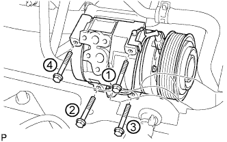
Provisionally tighten the compressor and magnetic clutch with the 4 bolts.
-
Tighten the compressor and magnetic clutch with the 4 bolts.
- Torque:
- 25 N*m { 255 kgf*cm, 18 ft.*lbf }
Note
Tighten the bolts in the order shown in the illustration to install the compressor and magnetic clutch.
-
-
INSTALL FAN & GENERATOR V BELT
-
Rotate the V-ribbed belt tensioner pulley clockwise, and then install the fan and generator V belt.
Note
Make sure that the fan and generator V belt is set properly on each pulley.
-
Check that the indicator mark of the V-ribbed belt tensioner Click here.
-
-
ADD ENGINE COOLANT
-
Firmly tighten the drain plugs.
-
Fill the radiator reservoir assembly with engine coolant to the top of the inlet.
Standard Capacity Item Specified Condition w/o Heater 13.2 liters (13.9 US qts, 11.6 Imp. qts) w/ Front Heater 14.2 liters (15.0 US qts, 12.5 Imp. qts) w/ Front and Rear Heaters 16.2 liters (17.1 US qts, 14.3 Imp. qts) Note
Do not substitute plain water for engine coolant.
Tech Tips
-
Use of improper coolants may damage the engine cooling system.
-
Use only Toyota Super Long Life Coolant or similar high quality ethylene glycol based non-silicate, non-amine, non-nitrite, and non-borate coolant with long-life hybrid organic acid technology (coolant with long-life hybrid organic acid technology consists of a combination of low phosphates and organic acids).
-
-
Loosen the bleeder plug of the outlet housing.
-
When air is bled and the engine coolant drains out, firmly tighten the bleeder plug.
- Torque:
- 8.0 N*m { 82 kgf*cm, 71 in.*lbf }
-

Add engine coolant up to the B line mark in the radiator reservoir assembly and install the radiator reservoir cap sub-assembly.
-
Warm up the engine until the thermostat opens.
-
While the thermostat is open, circulate the engine coolant for several minutes.
Tech Tips
The thermostat open timing can be confirmed by pressing the No. 3 radiator hose by hand, and checking when the engine coolant starts to flow inside the hose.
-
-

After the engine cools down, check that the engine coolant level is between the LOW and FULL level marks.
-
-
CONNECT CABLE TO NEGATIVE BATTERY TERMINAL
-
INSTALL BATTERY SERVICE HOLE COVER (W/ SUB BATTERY)
-
CHECK FOR ENGINE COOLANT LEAKS
-
INSTALL FENDER APRON MUDGUARD SEAL RH
-
INSTALL ENGINE SERVICE HOLE SUB COVER SUB-ASSEMBLY
-
Install the engine service hole sub cover with the 5 bolts.
- Torque:
- 13 N*m { 133 kgf*cm, 10 ft.*lbf }
-
-
INSTALL FRONT SEAT ASSEMBLY RH (for Hi-back Seat Type)
-
Perform the same procedure as above on the opposite side. Click here
-
-
INSTALL FRONT SEAT ASSEMBLY RH (for Low-back Seat Type)
-
Perform the same procedure as above on the opposite side. Click here
-
-
INSTALL FRONT DOOR SCUFF PLATE RH
-
INSTALL ENGINE UNDER COVER NO.2 (w/ Engine Under Cover No.2)
-
Install the engine under cover No.2 together with the engine side under cover LH and engine side under cover RH (for Wide Body).
- Torque:
- 13 N*m { 133 kgf*cm, 10 ft.*lbf }
-
-
INSTALL ENGINE UNDER COVER NO.1 (w/ Engine Under Cover No.1)
- Torque:
- 13 N*m { 133 kgf*cm, 10 ft.*lbf }
-
PERFORM INITIALIZATION