TURBOCHARGER INSTALLATION

-
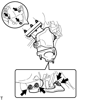
INSTALL NO. 1 TURBO WATER PIPE SUB-ASSEMBLY
-
Install a new gasket and the No. 1 turbo water pipe with the bolt and 2 nuts.
- Torque:
- for bolt
- 8.0 N*m { 82 kgf*cm, 71 in.*lbf }
- for nut
- 12 N*m { 122 kgf*cm, 9 ft.*lbf }
-
-
INSTALL COMPRESSOR INLET ELBOW
-
Install a new gasket and the compressor inlet elbow with the 2 nuts.
- Torque:
- 19 N*m { 194 kgf*cm, 14 ft.*lbf }
-
w/ DPF:
Connect the No. 4 turbo water hose.
-
-
TEMPORARILY INSTALL TURBOCHARGER
-
w/ DPF:
-
Set the turbocharger in a safe location.
-
Temporarily install the exhaust manifold with the 8 plate washers, 8 new nuts and 8 new collars.
-
Connect the 3 turbo water hoses.
-
-
w/o DPF:
-
Install the No. 2 water by-pass pipe with the bolt and 2 nuts.
- Torque:
- for bolt
- 19 N*m { 194 kgf*cm, 14 ft.*lbf }
- for nut
- 8.0 N*m { 82 kgf*cm, 71 in.*lbf }
-
Connect the 2 turbo water hoses.
-
-
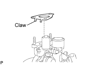
Install a new gasket to the turbocharger.
Note
Install the gasket in the correct direction.
-
Temporarily install the turbocharger with 3 new nuts.
-
-
TEMPORARILY INSTALL TURBO OIL INLET PIPE SUB-ASSEMBLY
-
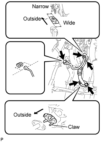
Install a new gasket to the turbo oil inlet pipe.
Note
Install the gasket in the correct direction.
-
Temporarily install the turbo oil inlet pipe with the 2 bolts, 2 nuts and union bolt.
-
-
TEMPORARILY INSTALL TURBOCHARGER STAY
-
Temporarily install the turbocharger stay with the 2 bolts and a new nut.
-
-
TIGHTEN TURBOCHARGER
-
w/ DPF:
Tighten the 8 nuts to the specified torque to install the exhaust manifold.
- Torque:
- 40 N*m { 408 kgf*cm, 30 ft.*lbf }
-
Tighten the 3 nuts to the specified torque to install the turbocharger.
- Torque:
- 52 N*m { 530 kgf*cm, 38 ft.*lbf }
-
-
CONNECT TURBOCHARGER STROKE SENSOR CONNECTOR
-
TIGHTEN TURBOCHARGER STAY
-
Tighten the 2 bolts and nut to the specified torque to install the turbocharger stay.
- Torque:
- 38 N*m { 387 kgf*cm, 28 ft.*lbf }
-
-
TIGHTEN TURBO OIL INLET PIPE SUB-ASSEMBLY
-
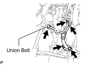
Tighten the 2 bolts, 2 nuts and union bolt to install the turbo oil inlet pipe.
- Torque:
- for bolt
- 12 N*m { 122 kgf*cm, 9 ft.*lbf }
- for nut
- 13 N*m { 133 kgf*cm, 10 ft.*lbf }
- for union bolt
- 26 N*m { 265 kgf*cm, 19 ft.*lbf }
-
-
INSTALL NO. 1 AUTOMATIC TRANSMISSION OIL COOLER TUBE CLAMP (for Automatic Transmission)
-
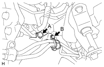
Install the clamp with the 2 bolts.
- Torque:
- for bolt A
- 71 N*m { 724 kgf*cm, 52 ft.*lbf }
- for bolt B
- 5.0 N*m { 51 kgf*cm, 44 in.*lbf }
-
-
INSTALL EXHAUST MANIFOLD CONVERTER SUB-ASSEMBLY (w/o DPF)
-
Install a new gasket and the exhaust manifold converter with 3 new nuts.
- Torque:
- 26 N*m { 260 kgf*cm, 19 ft.*lbf }
-
-
TEMPORARILY INSTALL TURBINE OUTLET ELBOW STAY
-
w/ DPF:
Temporarily install the turbine outlet elbow stay with the 2 bolts.
Tech Tips
The bolts are tightened after installing the catalytic with pipe converter assembly. The nuts are temporarily installed at that point and tightened after installing the front exhaust pipe.
-
w/o DPF:
-
Temporarily install the turbine outlet elbow stay with the 2 bolts and 2 new nuts.
Tech Tips
The nuts are tightened after installing the front exhaust pipe.
-
Tighten the 2 bolts.
- Torque:
- 62 N*m { 632 kgf*cm, 46 ft.*lbf }
-
-
-
TEMPORARILY INSTALL NO. 1 EXHAUST MANIFOLD HEAT INSULATOR
-
Temporarily install the No. 1 exhaust manifold heat insulator with the 3 bolts.
-
-
INSTALL TURBO INSULATOR
-
Temporarily install the turbo insulator with the 2 bolts.
-
Tighten the 5 bolts to the specified torque to install the turbo insulator and No. 1 exhaust manifold heat insulator.
- Torque:
- 12 N*m { 122 kgf*cm, 9 ft.*lbf }
-
-
INSTALL TURBINE OUTLET ELBOW (w/ DPF)
-
Temporarily install the turbine outlet elbow and a new gasket with 3 new nuts.
-
Temporarily install the No. 3 fuel pipe and a new gasket with the union bolt.
-
Tighten the 3 nuts of the turbine outlet elbow.
- Torque:
- 30 N*m { 306 kgf*cm, 22 ft.*lbf }
-
-
INSTALL NO. 2 FUEL PIPE CLAMP (w/ DPF)
-
Temporarily install the No. 2 fuel pipe clamp with the 2 bolts.
-
Tighten the 2 bolts of the No. 2 fuel pipe clamp and the union bolt of the No. 3 fuel pipe.
- Torque:
- for bolt
- 8.0 N*m { 82 kgf*cm, 71 in.*lbf }
- for union bolt
- 30 N*m { 306 kgf*cm, 22 ft.*lbf }
-
Connect the No. 4 water by-pass pipe to the No. 13 water by-pass hose.
-
Install a new gasket to the turbine outlet elbow with the union bolt.
- Torque:
- 40 N*m { 408 kgf*cm, 30 ft.*lbf }
-
-
INSTALL CATALYTIC WITH PIPE CONVERTER ASSEMBLY (w/ DPF)
-
Install a new gasket and the catalytic with pipe converter with 3 new nuts.
- Torque:
- 30 N*m { 306 kgf*cm, 22 ft.*lbf }
-
Temporarily install 2 new nuts.
Tech Tips
The nuts are tightened after installing the front exhaust pipe.
-
Tighten the 2 bolts of the turbine outlet elbow stay.
- Torque:
- 62 N*m { 632 kgf*cm, 46 ft.*lbf }
-
-
INSTALL NO. 3 EXHAUST MANIFOLD HEAT INSULATOR (w/ DPF)
-
Install the No. 3 exhaust manifold heat insulator with the 2 bolts.
- Torque:
- 13 N*m { 133 kgf*cm, 10 ft.*lbf }
-
-
INSTALL NO. 2 EXHAUST MANIFOLD HEAT INSULATOR (w/ DPF)
-
Install the No. 2 exhaust manifold heat insulator with the 2 bolts.
- Torque:
- 13 N*m { 133 kgf*cm, 10 ft.*lbf }
-
-
INSTALL WIRE HARNESS CLAMP BRACKET
-
Install the wire harness clamp bracket with the bolt.
- Torque:
- 9.0 N*m { 92 kgf*cm, 80 in.*lbf }
-
Attach the 3 wire harness clamps.
-
-
INSTALL VENTILATION PIPE
-
Install the ventilation pipe with the bolt.
- Torque:
- 20 N*m { 204 kgf*cm, 15 ft.*lbf }
-
Connect to the 2 ventilation hoses.
-
-
INSTALL NO. 1 COMPRESSOR MOUNTING BRACKET (w/ Air Conditioning System)
-
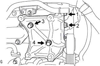
Temporarily install the No. 1 compressor mounting bracket with the 4 bolts.
Tech Tips
Make sure that the No. 1 compressor mounting bracket is in contact with the cylinder block.
-
Tighten the 4 bolts in the sequence shown in the illustration.
- Torque:
- 45 N*m { 459 kgf*cm, 33 ft.*lbf }
-
-
INSTALL COMPRESSOR OUTLET ELBOW
-
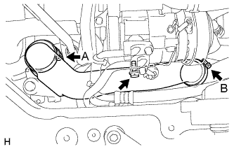
Install the compressor outlet elbow with the 2 hose clamps and bolt.
- Torque:
- for bolt
- 12 N*m { 122 kgf*cm, 9 ft.*lbf }
- for hose clamp A
- 6.5 N*m { 66 kgf*cm, 58 in.*lbf }
- for hose clamp B
- 6.0 N*m { 61 kgf*cm, 53 in.*lbf }
-
-
INSTALL COMPRESSOR ELBOW STAY
-
Install the compressor elbow stay with the 2 bolts.
- Torque:
- 20 N*m { 204 kgf*cm, 15 ft.*lbf }
-
-
CONNECT TURBOCHARGER MOTOR CONNECTOR
-
INSTALL AIR TUBE ASSEMBLY
-
Install the air tube with the 2 hose clamps and 2 bolts.
- Torque:
- for bolt A
- 18 N*m { 184 kgf*cm, 13 ft.*lbf }
- for bolt B
- 7.0 N*m { 71 kgf*cm, 62 in.*lbf }
- for hose clamp
- 4.5 N*m { 46 kgf*cm, 40 in.*lbf }
-
-
INSTALL NO. 1 AIR CLEANER HOSE
-
Install the No. 1 air cleaner hose to the compressor inlet elbow.
Note
Pull the hose to make sure that it is locked and securely connected.
-
-
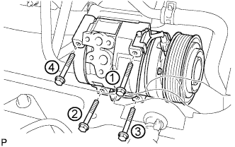
INSTALL COMPRESSOR AND MAGNETIC CLUTCH (w/ Air Conditioning System)
-
Provisionally tighten the compressor and magnetic clutch with the 4 bolts.
-
Tighten the compressor and magnetic clutch with the 4 bolts.
- Torque:
- 25 N*m { 255 kgf*cm, 18 ft.*lbf }
Note
Tighten the bolts in the order shown in the illustration to install the compressor and magnetic clutch.
-
-
CONNECT NO. 1 COOLER REFRIGERANT SUCTION HOSE (w/ Air Conditioning System)
-
CONNECT NO. 1 COOLER REFRIGERANT DISCHARGE HOSE (w/ Air Conditioning System)
-
INSTALL FAN AND GENERATOR V BELT (w/ Air Conditioning System)
-
Rotate the V-ribbed belt tensioner pulley clockwise, and then install the fan and generator V belt.
Note
Make sure that the fan and generator V belt is set properly on each pulley.
-
Check that the indicator mark of the V-ribbed belt tensioner Click here.
-
-
INSTALL NO. 1 TRANSMISSION CONTROL CABLE BRACKET (for Manual Transmission)
-
Install the transmission control cable bracket with the 2 bolts.
- Torque:
- 72 N*m { 729 kgf*cm, 53 ft.*lbf }
-
-
CONNECT TRANSMISSION CONTROL CABLE ASSEMBLY (for Manual Transmission)
-
Install 2 new clips to the No. 1 transmission control cable bracket.
-
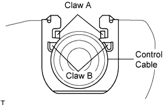
Connect the transmission control cable assembly to the No. 1 transmission control cable bracket.
Note
-
Make sure that A claws of the clips are firmly installed into the bracket grooves.
-
Make sure that the cable is set in the clip with both B claws erected to prevent slippage of the cable in the opposite direction.
-
-
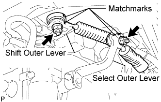
Align the matchmarks on the control cable assembly and the shift outer lever.
-
Align the matchmarks on the control cable assembly and the select outer lever.
-
Install the transmission control cable assembly to the shift outer lever with the nut.
- Torque:
- 37 N*m { 377 kgf*cm, 27 ft.*lbf }
-
Install the transmission control cable assembly to the select outer lever with the nut.
- Torque:
- 37 N*m { 377 kgf*cm, 27 ft.*lbf }
-
-
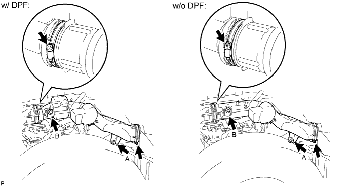
INSTALL FRONT EXHAUST PIPE ASSEMBLY (w/ DPF)
-
INSTALL FRONT EXHAUST PIPE ASSEMBLY (w/o DPF)
-
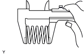
Inspect the compression spring.
-
Using vernier calipers, measure the free length of the compression spring.
Minimum length 40.5 mm (1.59 in.) If the free length is less than the minimum, replace the compression spring.
-
-
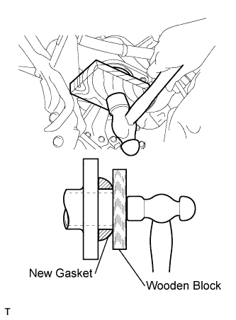
Fully push a new gasket onto the exhaust manifold converter pipe by hand.
-
Using a wooden block, uniformly strike the gasket so that the gasket and exhaust manifold converter fit together properly.
Note
-
Install the gasket in the correct direction.
-
Do not damage the outer surface of the gasket.
-
Do not reuse the removed gasket.
-
Do not push in the gasket with the front exhaust pipe when connecting the pipe.
-
-
Connect the front exhaust pipe to the No. 4 exhaust pipe support.
-
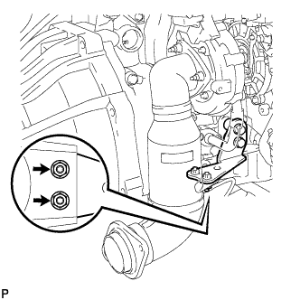
Install the front exhaust pipe and 2 compression springs with the 2 bolts and 2 nuts.
- Torque:
- for bolt
- 43 N*m { 438 kgf*cm, 32 ft.*lbf }
- for nut
- 48 N*m { 489 kgf*cm, 35 ft.*lbf }
-
-
TIGHTEN EXHAUST MANIFOLD CONVERTER SUB-ASSEMBLY (w/o DPF)
-
Tighten the 2 nuts to the exhaust manifold converter.
- Torque:
- 62 N*m { 632 kgf*cm, 46 ft.*lbf }
-
-
CONNECT CABLE TO NEGATIVE BATTERY TERMINAL
-
ADD ENGINE COOLANT
-
CHARGE REFRIGERANT (w/ Air Conditioning System)
-
WARM UP ENGINE
-
CHECK FOR REFRIGERANT LEAK (w/ Air Conditioning System)
-
INSPECT FOR COOLANT LEAK
-
INSPECT FOR OIL LEAK
-
INSPECT FOR EXHAUST GAS LEAK
If gas is leaking, tighten the areas necessary to stop the leak. Replace damaged parts as necessary.
-
INSTALL FENDER APRON MUDGUARD SEAL RH
-
INSTALL ENGINE SERVICE HOLE SUB COVER SUB-ASSEMBLY
-
Install the engine service hole sub cover with the 5 bolts.
- Torque:
- 13 N*m { 133 kgf*cm, 10 ft.*lbf }
-
-
INSTALL FRONT SEAT ASSEMBLY RH
-

Connect the front seat inner belt assembly connector and install the front seat assembly.
-
Align the front seat assembly adjuster pin with the holes in the body.
-
Move the front seat assembly to the rearmost position.
Note
Make sure that the front seat assembly is securely locked.
-
Temporarily tighten the 2 bolts on the front side of the front seat assembly.
-
Move the front seat assembly fully forward.
Note
Make sure that the front seat assembly is securely locked.
-
Temporarily tighten the 2 bolts on the rear side of the front seat assembly.
-
Move the front seat assembly to the rearmost position.
Note
Make sure that the front seat assembly is securely locked.
-
Fully tighten the 2 bolts on the front side of the front seat assembly in the order of outer and inner side.
- Torque:
- 39 N*m { 398 kgf*cm, 29 ft.*lbf }
-
Move the front seat assembly fully forward.
Note
Make sure that the front seat assembly is securely locked.
-
Fully tighten the 2 bolts on the rear side of the front seat assembly in the order of outer and inner side.
- Torque:
- 39 N*m { 398 kgf*cm, 29 ft.*lbf }
-
-
INSTALL FRONT DOOR SCUFF PLATE RH
-
INSTALL NO. 2 ENGINE UNDER COVER (for Cold Area Specification Vehicles)
-
Install the No. 2 engine under cover with the 6 bolts.
- Torque:
- 13 N*m { 133 kgf*cm, 10 ft.*lbf }
-
-
INSTALL NO. 1 ENGINE UNDER COVER (for Cold Area Specification Vehicles)
-
Install the No. 1 engine under cover with the 4 bolts.
- Torque:
- 13 N*m { 133 kgf*cm, 10 ft.*lbf }
-