TURBOCHARGER REMOVAL

-
REMOVE NO. 1 ENGINE UNDER COVER (for Cold Area Specification Vehicles)
-
Remove the 4 bolts and No. 1 engine under cover.
-
-
REMOVE NO. 2 ENGINE UNDER COVER (for Cold Area Specification Vehicles)
-
Remove the 6 bolts and No. 2 engine under cover.
-
-
DRAIN ENGINE COOLANT
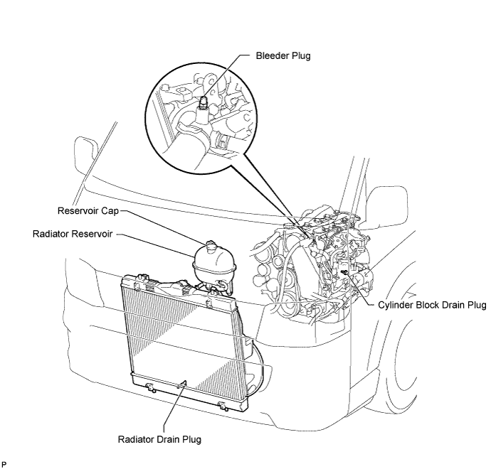
CAUTION:
To avoid the danger of being burned, do not remove the reservoir cap while the engine and radiator are still hot. Thermal expansion will cause hot engine coolant and steam to blow out from the radiator.
-
Loosen the radiator drain plug.
-
Remove the reservoir cap.
-
Loosen the cylinder block drain plug (on the engine oil cooler cover), and drain the coolant.
-
Tighten the radiator drain plug.
-
Tighten the cylinder block drain plug (on the engine oil cooler cover).
- Torque:
- 8.0 N*m { 82 kgf*cm, 71 in.*lbf }
-
-
DISCONNECT CABLE FROM NEGATIVE BATTERY TERMINAL
-
RECOVER REFRIGERANT FROM REFRIGERATION SYSTEM (w/ Air Conditioning System)
-
Start up the engine.
-
Turn the A/C switch on.
-
Operate the cooler compressor at an engine rpm of approximately 1,000 for 5 to 6 minutes to circulate the refrigerant and collect compressor oil remaining in each component into the cooler compressor as much as possible.
-
Stop the engine.
-
Using SST, let the refrigerant gas out.
- SST
- 07110-58060 ( 07117-58080, 07117-58090, 07117-78050, 07117-88060, 07117-88070, 07117-88080 )
-
-
REMOVE FRONT DOOR SCUFF PLATE RH
-
REMOVE FRONT SEAT ASSEMBLY RH
-

Move the front seat assembly fully forward.
-
Remove the 2 bolts on the rear side of the seat.
-
Move the front seat assembly to the rearmost position.
-
Remove the 2 bolts on the front side of the seat.
-
Move the front seat assembly to the center of the seat slide rail. Set the seatback in the upright position.
-
Disconnect the front seat inner belt assembly connector.
-
Remove the front seat assembly.
-
-
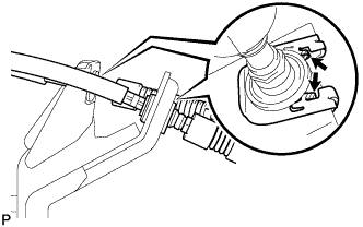
REMOVE ENGINE SERVICE HOLE SUB COVER SUB-ASSEMBLY
-
Roll up the carpet and remove the engine service hole sub cover.
-
-
REMOVE FENDER APRON MUDGUARD SEAL RH
-
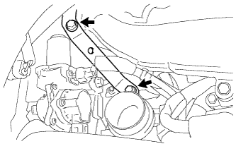
REMOVE FAN AND GENERATOR V BELT
-
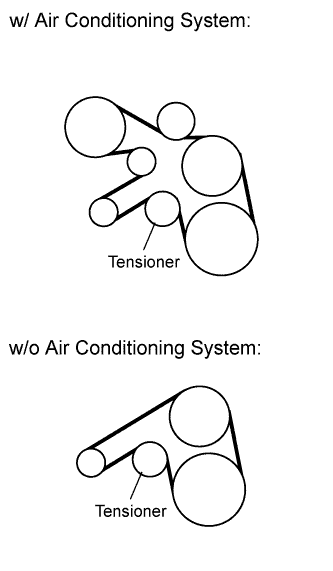
Remove the drive belt by rotating the tensioner pulley clockwise to loosen its tension with the pulley set bolt of the tensioner.
-
-
DISCONNECT NO. 1 COOLER REFRIGERANT DISCHARGE HOSE (w/ Air Conditioning System)
-
DISCONNECT NO. 1 COOLER REFRIGERANT SUCTION HOSE (w/ Air Conditioning System)
-
REMOVE COMPRESSOR AND MAGNETIC CLUTCH (w/ Air Conditioning System)
-
Disconnect the connector.
-
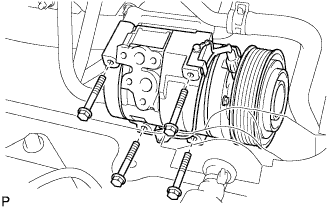
Remove the 4 bolts and compressor and magnetic clutch.
-
-
REMOVE FRONT EXHAUST PIPE ASSEMBLY (w/ DPF)
-
REMOVE FRONT EXHAUST PIPE ASSEMBLY (w/o DPF)
-
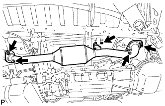
Remove the 2 bolts, 2 nuts and 2 compression springs.
-
Disconnect the front exhaust pipe from the No. 4 exhaust pipe support.
-
Remove the 2 gaskets.
-
-
DISCONNECT TRANSMISSION CONTROL CABLE ASSEMBLY (for Manual Transmission)
-
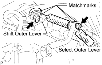
Put matchmarks on the transmission control cable assembly and the select outer lever.
-
Put matchmarks on the transmission control cable assembly and the shift outer lever.
-
Remove the nut and disconnect the transmission control cable assembly from the select outer lever.
-
Remove the nut and disconnect the transmission control cable assembly from the shift outer lever.
-
Using a screwdriver, disengage the claws of the 2 clips.
-
Remove the 2 transmission control cable assemblies and 2 clips from the No. 1 transmission control cable bracket.
-
-
REMOVE NO. 1 TRANSMISSION CONTROL CABLE BRACKET (for Manual Transmission)
-
Remove the 2 bolts and No. 1 transmission control cable bracket.
-
-
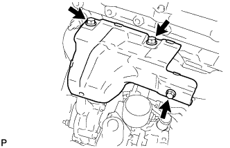
REMOVE NO. 2 EXHAUST MANIFOLD HEAT INSULATOR (w/ DPF)
-
Remove the 2 bolts and No. 2 exhaust manifold heat insulator.
-
-
REMOVE NO. 3 EXHAUST MANIFOLD HEAT INSULATOR (w/ DPF)
-
Remove the 2 bolts and No. 3 exhaust manifold heat insulator.
-
-
REMOVE CATALYTIC WITH PIPE CONVERTER ASSEMBLY (w/ DPF)
-
Remove the 2 nuts from the catalytic with pipe converter.
-
Remove the 3 nuts, catalytic with pipe converter and gasket.
-
-
REMOVE NO. 2 FUEL PIPE CLAMP (w/ DPF)
-
Loosen the union bolt of the No. 3 fuel pipe.
-
Remove the 2 bolts and No. 2 fuel pipe clamp.
-
-
REMOVE TURBINE OUTLET ELBOW (w/ DPF)
-
Disconnect the fuel addition injector connector and No. 1 turbo water hose.
-
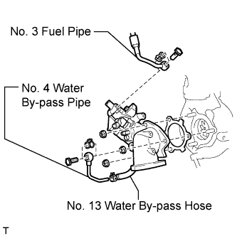
Remove the 2 union bolts and 2 gaskets from the turbine outlet elbow.
-
Disconnect the No. 4 water by-pass pipe from the No. 13 water by-pass hose.
-
Remove the 3 nuts, turbine outlet elbow and gasket.
-
-
DISCONNECT NO. 1 AIR CLEANER HOSE
-
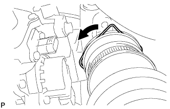
Pull the stopper upward and disconnect the No. 1 air cleaner hose from the compressor inlet elbow.
-
-
REMOVE AIR TUBE ASSEMBLY
-
Loosen the 2 hose clamps.
-
Remove the 2 bolts, air tube and No. 1 air cleaner hose.
-
-
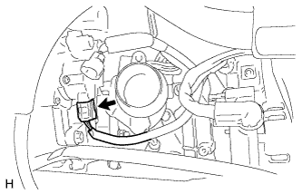
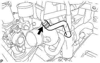
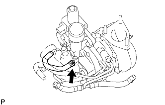
DISCONNECT TURBOCHARGER MOTOR CONNECTOR
-
REMOVE COMPRESSOR ELBOW STAY
-
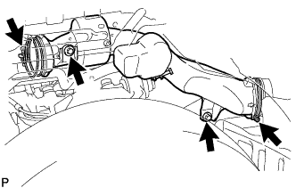
Remove the 2 bolts and compressor elbow stay.
-
-
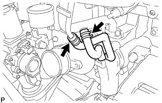
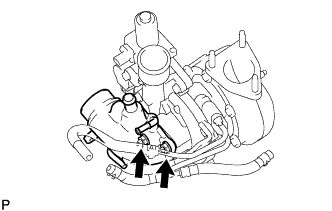
REMOVE COMPRESSOR OUTLET ELBOW
-
Loosen the 2 hose clamps and remove the bolt and compressor outlet elbow.
-
-
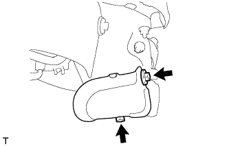
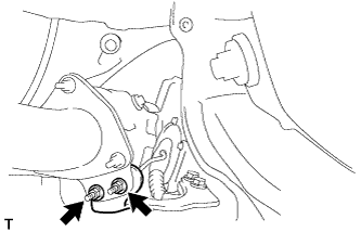
REMOVE NO. 1 COMPRESSOR MOUNTING BRACKET (w/ Air Conditioning System)
-
Remove the 4 bolts and No. 1 compressor mounting bracket.
-
-
REMOVE WIRE HARNESS CLAMP BRACKET
-
Detach the 3 clamps.
-
Remove the bolt and wire harness clamp bracket.
-
-
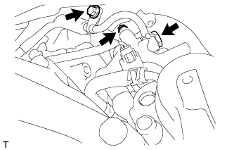
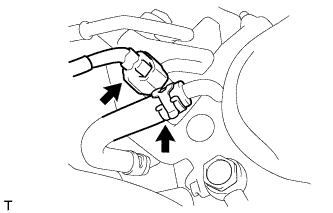
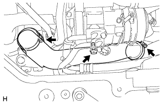
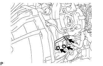
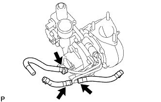
REMOVE VENTILATION PIPE
-
w/ DPF:
-
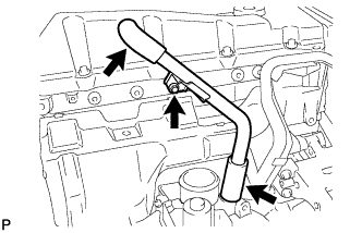
Remove the bolt and ventilation pipe.
-
Disconnect the 2 ventilation hoses.
-
-
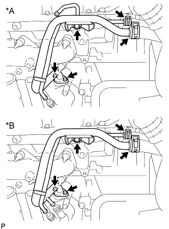
w/o DPF:
-
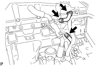
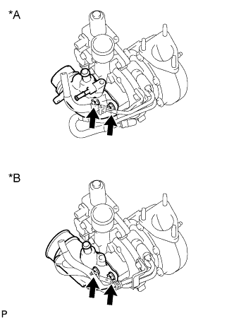
for LHD:
Remove the No. 14 water by-pass hose and disconnect the No. 4 turbo water hose.
-
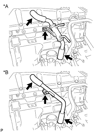
Text in Illustration *A for LHD *B for RHD Remove the bolt and ventilation pipe.
-
Disconnect the 2 ventilation hoses.
-
-
-
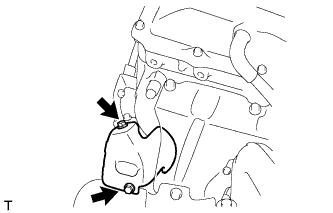
REMOVE TURBO INSULATOR
-
Remove the 2 bolts and turbo insulator.
-
-
REMOVE NO. 1 EXHAUST MANIFOLD HEAT INSULATOR
-
Remove the 3 bolts and No. 1 exhaust manifold heat insulator.
-
-
REMOVE TURBINE OUTLET ELBOW STAY
-
w/ DPF:
Remove the 2 bolts and turbine outlet elbow stay.
-
w/o DPF:
Remove the 2 bolts, 2 nuts and turbine outlet elbow stay.
-
-
REMOVE EXHAUST MANIFOLD CONVERTER SUB-ASSEMBLY (w/o DPF)
-
Remove the 3 nuts, exhaust manifold converter and gasket.
-
-
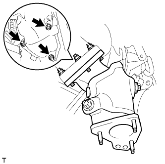
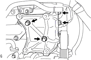
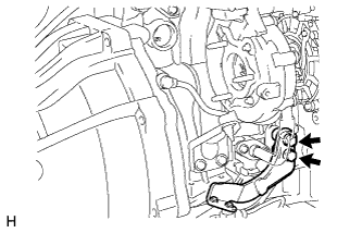
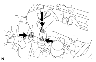
REMOVE TURBOCHARGER STAY
-
Remove the 2 bolts, nut and turbocharger stay.
-
-
REMOVE NO. 1 AUTOMATIC TRANSMISSION OIL COOLER TUBE CLAMP (for Automatic Transmission)
-
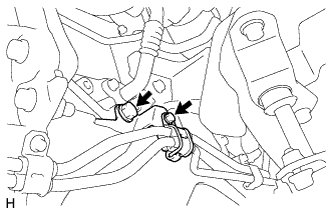
Remove the 2 bolts and No. 1 automatic transmission oil cooler tube clamp.
-
-
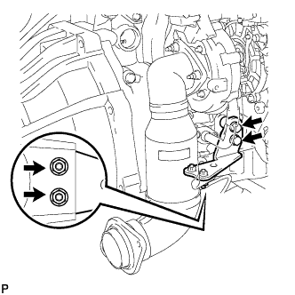
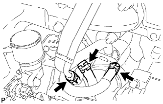
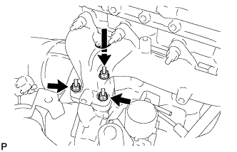
REMOVE TURBO OIL INLET PIPE SUB-ASSEMBLY
-
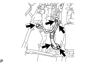
Remove the 2 bolts, 2 nuts and union bolt, and then remove the turbo oil inlet pipe and 3 gaskets.
Note
Do not loosen the nut as shown in the illustration. If the nut is mistakenly loosened, replace the turbocharger.
-
-
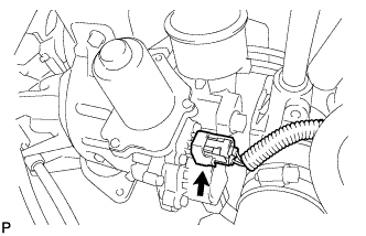
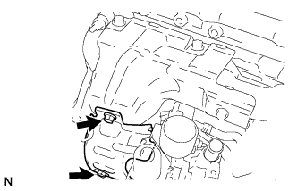
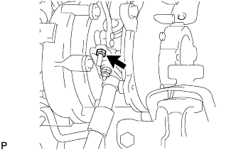
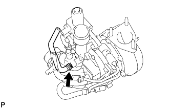
DISCONNECT TURBOCHARGER STROKE SENSOR CONNECTOR
-
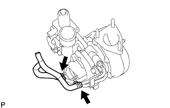
REMOVE TURBOCHARGER
-
w/ DPF:
-
Disconnect the 3 turbo water hoses.
-
Remove the 3 nuts and disconnect the turbocharger.
-
Temporarily place the turbocharger on the mounting bracket.
-
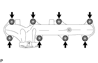
Remove the 8 nuts, 8 plate washers, 8 collars and exhaust manifold.
-
Remove the turbocharger and gasket.
-
-
w/o DPF:
-
Remove the 3 nuts and disconnect the turbocharger.
-
for LHD:
Disconnect the No. 2 turbo water hose.
-
for RHD:
Disconnect the No. 1 turbo water hose and No. 2 turbo water hose.
-
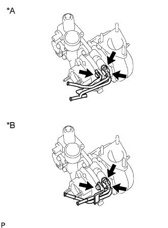
Text in Illustration *A for LHD *B for RHD Disconnect the 2 water hoses.
-
Remove the bolt, 2 nuts, No. 2 water by-pass pipe and gasket.
-
Remove the turbocharger and gasket.
-
-
-
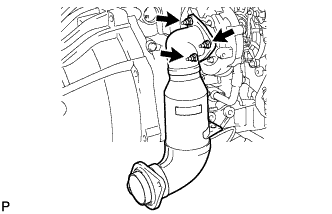
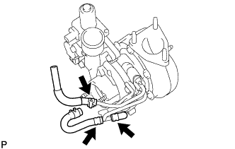
REMOVE COMPRESSOR INLET ELBOW
-
w/ DPF:
-
Remove the No. 4 turbo water hose.
-
Remove the 2 nuts, compressor inlet elbow and gasket.
-
-
w/o DPF:
-
for LHD:
Remove the No. 3 turbo water hose.
-
Text in Illustration *A for LHD *B for RHD Remove the 2 nuts, compressor inlet elbow and gasket.
-
-
-
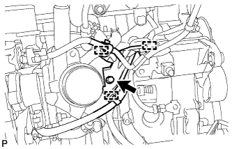
REMOVE NO. 1 TURBO WATER PIPE SUB-ASSEMBLY
-
w/ DPF:
-
Remove the turbo water hose, No. 2 turbo water hose and No. 13 turbo water hose.
-
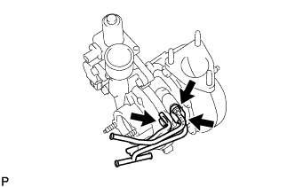
Remove the bolt, 2 nuts, No. 1 turbo water pipe and gasket.
-
-
w/o DPF:
-
for LHD:
Remove the No. 2 turbo water hose, No. 3 turbo water hose and plug.
-
for RHD:
Remove the No. 1 turbo water hose and No. 2 turbo water hose.
-
Text in Illustration *A for LHD *B for RHD Remove the bolt, 2 nuts, No. 1 turbo water pipe and gasket.
-
-