EMISSION CONTROL SYSTEM ON-VEHICLE INSPECTION

-
INSPECT AIR-FUEL RATIO COMPENSATION SYSTEM
-
VISUALLY CHECK HOSES, CONNECTIONS AND GASKETS
-
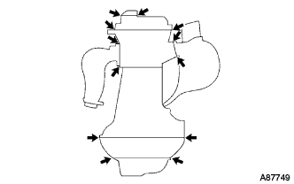
Check that there are no cracks, leaks or damage.
Note
-
Detachment or other problems with the engine oil dipstick, filler cap, PCV hose and other components may cause the engine to run improperly.
-
Air suction caused by disconnections, looseness or cracks in the parts of the air induction system between the throttle body and cylinder head will cause engine failure or engine malfunctions.
If any defects are found, replace the parts as necessary.
-
-
-
INSPECT AIR-FUEL RATIO COMPENSATION SYSTEM (Unleaded Gasoline w/ Secondary Air Injection)
Tech Tips
This system can also be checked using the intelligent tester. Switch to DATA MONITOR mode and select O2 SENSOR OUTPUT VOLTAGE.
-
Inspect the air fuel ratio sensor.
-
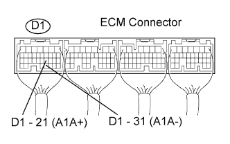
Connect the intelligent tester to terminals A1A+ (D1-21) and A1A- (D1-31) of the ECM.
Note
Connect test leads to the connector's backside. The connectors should not be disconnected from the ECM.
-
Warm up the air fuel ratio sensor with the engine speed at 2,500 rpm for approximately 2 minutes.
-
Check that the voltage changes between 0 V and 1 V with the engine speed at 2,500 rpm.
OK The voltage has changed more than 8 times in 10 seconds. Note
-
Check the voltage immediately after warming up the air fuel ratio sensor.
-
If change of voltage could not be confirmed, warm up the air fuel ratio sensor again.
-
-
-
Inspect the oxygen sensor.
-
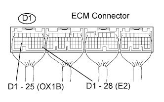
Connect the intelligent tester to terminals OX1B (D1-25) and E2 (D1-28) of the ECM.
Note
Connect tester leads to the connector's backside. The connectors should not be disconnected from the ECM.
-
Warm up the heated oxygen sensor with the engine speed at 2,500 rpm for approximately 2 minutes.
-
Check that the voltage changes between 0 V and 1 V with the engine speed at 2,500 rpm.
OK The voltage has changed more than 8 times in 10 seconds. Note
-
Check the voltage immediately after warming up the heated oxygen sensor.
-
If change of voltage could not be confirmed, warm up the heated oxygen sensor again.
-
-
-
-
INSPECT AIR-FUEL RATIO COMPENSATION SYSTEM (Unleaded Gasoline w/o Secondary Air Injection)
Tech Tips
This system can also be checked using the intelligent tester. Switch to DATA MONITOR mode and select O2 SENSOR OUTPUT VOLTAGE.
-
Inspect the oxygen sensor.
-

Connect the intelligent tester to terminals OX1A (D1-21) and E2 (D1-28) of the ECM.
Note
Connect tester leads to the connector's backside. The connectors should not be disconnected from the ECM.
-
Warm up the heated oxygen sensor with the engine speed at 2,500 rpm for approximately 2 minutes.
-
Check that the voltage changes between 0 V and 1 V with the engine speed at 2,500 rpm.
OK The voltage has changed more than 8 times in 10 seconds. Note
-
Check the voltage immediately after warming up the heated oxygen sensor.
-
If change of voltage could not be confirmed, warm up the heated oxygen sensor again.
-
-
-
-
INSPECT DUTY VACUUM SWITCHING VALVE (EVAP VSV)
-
Check if the vacuum hose is connected correctly.
-
Disconnect the vacuum hose from the charcoal canister, and connect a vacuum gauge.
-
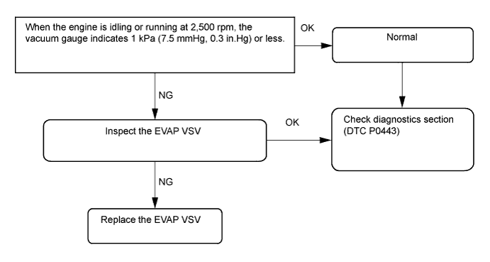
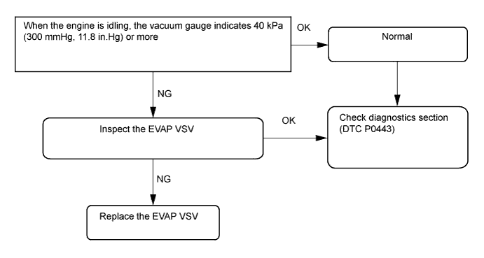
Using the flowchart below, perform an EVAP VSV operation inspection when the engine coolant temperature is 55°C (131°F) or less (while the engine is cold (VSV is closed)).
Tech Tips
The ECM turns the VSV off so that the route between the charcoal canister and intake manifold is closed, and fuel vapor in the canister is not purged to the intake manifold.
-
EVAP VSV operation flowchart.
-
-
Using the flowchart below, perform an EVAP VSV operation inspection when the engine coolant temperature is 80°C (176°F) or more (while the engine is hot (VSV is opened)).
Tech Tips
The ECM turns the VSV on so that a vacuum is created in the intake manifold and the charcoal canister's fuel vapor is purged to the intake manifold.
-
EVAP VSV operation flowchart.
-
-