EGR COOLER (w/o DPF) INSTALLATION

-
INSTALL NO. 1 EGR PIPE SUB-ASSEMBLY
-
Install a new gasket and the No. 1 EGR pipe with the 2 nuts.
- Torque:
- 13 N*m { 133 kgf*cm, 10 ft.*lbf }
-
-
INSTALL EGR COOLER ASSEMBLY
-
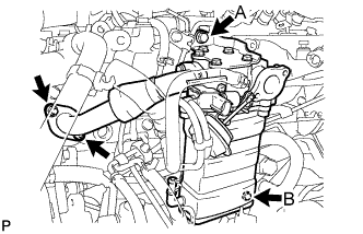
Install a new gasket and the EGR cooler with the 2 bolts and 2 nuts.
- Torque:
- for bolt A
- 22 N*m { 224 kgf*cm, 16 ft.*lbf }
- for bolt B
- 20 N*m { 204 kgf*cm, 15 ft.*lbf }
- for nut
- 13 N*m { 133 kgf*cm, 10 ft.*lbf }
-
-
CONNECT NO. 4 WATER BY-PASS HOSE
-
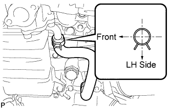
Connect the No. 4 water by-pass hose to the EGR cooler.
Tech Tips
The direction of the hose clamp is indicated in the illustration.
-
-
CONNECT WATER BY-PASS HOSE ASSEMBLY
-
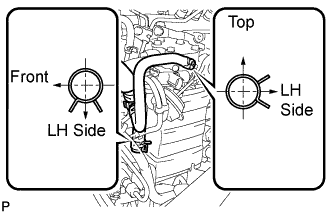
Connect the water by-pass hose to the EGR cooler.
Tech Tips
The direction of the hose clamp is indicated in the illustration.
-
-
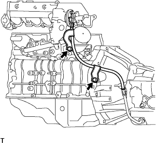
CONNECT NO. 4 VACUUM TRANSMITTING HOSE ASSEMBLY
-
Connect the No. 4 vacuum transmitting hose.
-
-
INSTALL ELECTRIC EGR CONTROL VALVE ASSEMBLY
-
Install the vacuum regulating valve with the 2 bolts.
- Torque:
- 20 N*m { 204 kgf*cm, 15 ft.*lbf }
-
Install a new gasket and the electric EGR valve to the intake air connector.
-
Install 2 new gaskets and the electric EGR valve together with the intake air connector to the intake manifold with the bolt and 2 nuts.
- Torque:
- 20 N*m { 204 kgf*cm, 15 ft.*lbf }
-
Connect the 2 vacuum hoses to the vacuum regulating valve.
-
Connect the vacuum regulating valve connector.
-
-
INSTALL MANIFOLD STAY
-
Install the manifold stay with the 2 bolts.
- Torque:
- 19 N*m { 194 kgf*cm, 14 ft.*lbf }
-
-
INSTALL VACUUM SWITCHING VALVE ASSEMBLY
-
Install the vacuum switching valve with the bolt.
- Torque:
- 20 N*m { 204 kgf*cm, 15 ft.*lbf }
-
Connect the connector and vacuum hose to the vacuum switching valve.
-
Attach the clamp and wire harness.
-
Connect the connector to the electric EGR control valve.
-
-
CONNECT NO. 1 GAS FILTER
-
Connect the vacuum hose together with the gas filter.
-
Install the bolt.
- Torque:
- 8.0 N*m { 82 kgf*cm, 71 in.*lbf }
-
-
INSTALL ENGINE OIL LEVEL DIPSTICK GUIDE
-
Install a new O-ring to the engine oil level dipstick guide.
-
Apply a small amount of clean engine oil to the O-ring.
-
Install the engine oil level dipstick guide with the bolt.
- Torque:
- 8.0 N*m { 82 kgf*cm, 72 in.*lbf }
-
-
INSTALL DIESEL THROTTLE BODY ASSEMBLY
-
INSTALL TRANSMISSION OIL FILLER TUBE SUB-ASSEMBLY (for Automatic Transmission)
-
Coat a new O-ring with ATF and install it onto the oil filler tube sub-assembly.
-
Install the oil filler tube sub-assembly with the 2 bolts.
- Torque:
- 12 N*m { 122 kgf*cm, 9 ft.*lbf }
-
-
INSTALL NO. 2 ENGINE SERVICE HOLE COVER (for Standard Body)
-
ADD ENGINE COOLANT
-
Firmly tighten the drain plugs.
-
Fill the radiator reservoir with coolant to the top of the inlet.
Standard Capacity Item Specified Condition w/o Heater 13.6 liters (14.4 US qts, 12.0 Imp. qts) w/ Front Heater 14.6 liters (15.4 US qts, 12.8 Imp. qts) w/ Front and Rear Heaters 16.6 liters (17.5 US qts, 14.6 Imp. qts) Note
Do not substitute plain water for engine coolant.
Tech Tips
-
Use of improper coolants may damage the engine cooling system.
-
Use only Toyota Super Long Life Coolant or similar high quality ethylene glycol based non-silicate, non-amine, non-nitrite, and non-borate coolant with long-life hybrid organic acid technology (coolant with long-life hybrid organic acid technology consists of a combination of low phosphates and organic acids).
-
-
Loosen the bleeder plug of the outlet housing.
-
When air is bled and the coolant drains out, firmly tighten the bleeder plug.
- Torque:
- 8.0 N*m { 82 kgf*cm, 71 in.*lbf }
-

Add coolant up to the B line mark in the radiator reservoir and install the reservoir cap.
-
Warm up the engine until the thermostat opens.
-
While the thermostat is open, circulate the coolant for several minutes.
Tech Tips
The thermostat open timing can be confirmed by pressing the inlet radiator hose by hand, and checking when the engine coolant starts to flow inside the hose.
-
-

After the engine cools down, check that the coolant level is between the LOW and FULL level marks.
-
-
INSPECT FOR ENGINE COOLANT LEAK
CAUTION:
Do not remove the radiator cap while the engine and radiator are still hot. Hot, pressurized engine coolant and steam may be released and cause serious burns.
-
Fill the radiator with coolant and attach a radiator cap tester to the radiator.
-
Warm up the engine.
-
Using a radiator cap tester, increase the pressure inside the radiator to 137 kPa (1.4 kgf/cm2, 19.9 psi), and check that the pressure does not drop.
Tech Tips
If the pressure drops, check the hoses, radiator and water pump for leaks. If no external leaks are found, check the heater core, cylinder block and cylinder head.
-
-
INSPECT FOR EXHAUST GAS LEAK
If gas is leaking, tighten the areas necessary to stop the leak. Replace damaged parts as necessary.
-
INSTALL NO. 2 ENGINE UNDER COVER (for Cold Area Specification Vehicles)
-
Install the No. 2 engine under cover with the 6 bolts.
- Torque:
- 13 N*m { 133 kgf*cm, 10 ft.*lbf }
-
-
INSTALL NO. 1 ENGINE UNDER COVER (for Cold Area Specification Vehicles)
-
Install the No. 1 engine under cover with the 4 bolts.
- Torque:
- 13 N*m { 133 kgf*cm, 10 ft.*lbf }
-