EGR COOLER (w/ DPF) INSTALLATION

Note
-
When replacing the injectors (including shuffling the injectors between the cylinders), common rail or cylinder head, it is necessary to replace the injection pipes with new ones.
-
When replacing the fuel supply pump, common rail, cylinder block, cylinder head, cylinder head gasket or timing gear case, it is necessary to replace the fuel inlet pipe with a new one.
-
After removing the injection pipes and fuel inlet pipe, clean them with a brush and compressed air.
-
INSTALL EGR COOLER INSULATOR
-
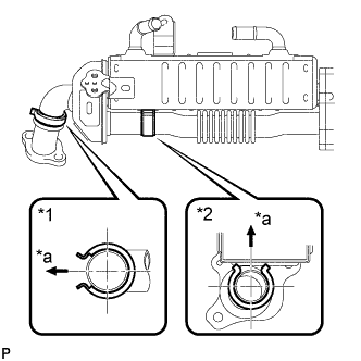
Text in Illustration *1 No. 1 EGR Insulator *2 No. 2 EGR Insulator *a Gap Install the No. 1 EGR cooler insulator and No. 2 EGR cooler insulator to the EGR cooler.
Tech Tips
Install the No. 1 EGR cooler insulator and No. 2 EGR cooler insulator so that they are positioned as shown in the illustration.
-
-
INSTALL NO. 2 EGR VALVE ASSEMBLY
-
Using a 6 mm hexagon wrench, install 2 new gaskets, No. 1 EGR valve adapter, No. 2 EGR valve assembly, EGR cooler and 3 plate washers with the 3 hexagon bolts.
- Torque:
- 28 N*m { 286 kgf*cm, 21 ft.*lbf }
-
-
TEMPORARILY INSTALL EGR COOLER WITH NO. 2 EGR VALVE ASSEMBLY
-
Install a new gasket to the stud bolts of the cylinder head sub-assembly.
-
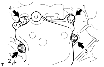
Install the No. 1 EGR valve adapter to the intake manifold with the bolt labeled A in the illustration.
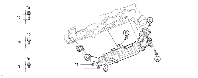
Text in Illustration *1 Nut - - *a Bolt A *b Bolt B *c Bolt C *d 25 mm (0.984 in.) *e 20 mm (0.787 in.) *f 14 mm (0.551 in.) -
Temporarily install the EGR cooler to the intake manifold with the bolt labeled B in the illustration.
-
Temporarily install the No. 2 EGR valve assembly with the bolt labeled C in the illustration.
-
Temporarily install the EGR cooler to the cylinder head sub-assembly with the 2 nuts.
-
-
TIGHTEN EGR COOLER WITH NO. 2 EGR VALVE ASSEMBLY
-
Tighten the bolt labeled A in the illustration.
- Torque:
- 20 N*m { 204 kgf*cm, 15 ft.*lbf }
-
Tighten the bolt labeled B in the illustration.
- Torque:
- 20 N*m { 204 kgf*cm, 15 ft.*lbf }
-
Tighten the bolt labeled C in the illustration.
- Torque:
- 13 N*m { 133 kgf*cm, 10 ft.*lbf }
-
Tighten the 2 nuts.
- Torque:
- 13 N*m { 133 kgf*cm, 10 ft.*lbf }
-
-
INSTALL FUEL INLET PIPE SUB-ASSEMBLY
Note
-
When replacing the fuel supply pump, common rail, cylinder block, cylinder head, cylinder head gasket or timing gear case, it is necessary to replace the fuel inlet pipe with a new one.
-
Keep the fuel inlet pipe free of foreign matter.
-
If a No. 1 injection pipe clamp is removed from the fuel inlet pipe, replace the No. 1 injection pipe clamp with a new one.
-
Temporarily install the fuel inlet pipe with the union nuts.
-
Install the 2 No. 1 injection pipe clamps with the 2 bolts.
- Torque:
- 6.5 N*m { 66 kgf*cm, 58 in.*lbf }
-
Using a 17 mm union nut wrench, tighten the fuel inlet pipe union nut on the common rail side.
- Torque:
- 35 N*m { 357 kgf*cm, 26 ft.*lbf }
Note
Use the formula to calculate special torque values for situations where a union nut wrench is combined with a torque wrench Click here.
-
Using a 17 mm union nut wrench, tighten the fuel inlet pipe union nut on the fuel supply pump side.
- Torque:
- 35 N*m { 357 kgf*cm, 26 ft.*lbf }
Note
Use the formula to calculate special torque values for situations where a union nut wrench is combined with a torque wrench Click here.
-
-
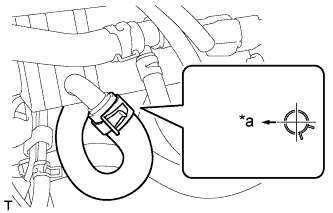
INSTALL WATER BY-PASS HOSE ASSEMBLY
-

Text in Illustration *a Front Side of Vehicle *b Top Install the water by-pass hose assembly to the water outlet and EGR cooler, and slide the 2 hose clamps to secure the hoses.
Tech Tips
The direction of each hose clamps is indicated in the illustration.
-
-
CONNECT NO. 3 WATER BY-PASS HOSE
-
Text in Illustration *a Front Side of Vehicle Connect the No. 3 water by-pass hose to the EGR cooler, and slide the hose clamp to secure the hose.
Tech Tips
The direction of the hose clamp is indicated in the illustration.
-
-
INSTALL INTAKE AIR TEMPERATURE SENSOR
-
Install a new gasket to the intake air temperature sensor.
-
Using a 22 mm ball joint lock nut wrench, install the intake air temperature sensor.
- Torque:
- 34 N*m { 350 kgf*cm, 25 ft.*lbf }
Note
Use the formula to calculate special torque values for situations where a ball joint lock nut wrench is combined with a torque wrench Click here.
-
Connect the intake air temperature sensor connector.
-
-
INSTALL INTAKE AIR CONNECTOR
-
Install a new gasket and the intake air connector with the 3 bolts.
- Torque:
- 20 N*m { 204 kgf*cm, 15 ft.*lbf }
-
-
TEMPORARILY INSTALL INTAKE AIR CONNECTOR ASSEMBLY
-
Using an E8 "TORX" socket wrench, install a new gasket and the intake air connector assembly with the 2 stud bolts.
- Torque:
- 12 N*m { 122 kgf*cm, 9 ft.*lbf }
Tech Tips
Install the 2 stud bolts after positioning the intake air connector assembly.
-
Temporarily install the 2 bolts and 2 nuts to the intake air connector assembly.
Note
Do not allow the cylinder head sub-assembly of the 2 bolts or the 2 nuts to contact the intake air connector assembly.
-
-
INSTALL ELECTRIC EGR CONTROL VALVE ASSEMBLY
-
Install the wiring harness connector to the electric EGR control valve.
-
Install a new gasket, the 2 stud bolts and the electric EGR control valve.
Tech Tips
Be sure to install the gasket together with the electric EGR control valve.
- Torque:
- 10 N*m { 102 kgf*cm, 7 ft.*lbf }
-
-
INSTALL INTAKE AIR CONNECTOR ASSEMBLY
-
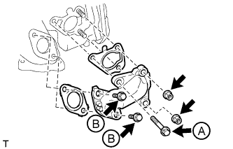
Temporarily install 2 new gaskets and the No. 2 EGR pipe sub-assembly with the 3 bolts and 2 nuts.
-
Tighten the bolt labeled A and 2 nuts shown in the illustration.
- Torque:
- 20 N*m { 204 kgf*cm, 15 ft.*lbf }
Note
The 2 bolts labeled B are tightened after fully tightening the 2 nuts and 2 bolts of the intake air connector assembly.
-
Tighten the 2 bolts and 2 nuts in the order shown in the illustration.
- Torque:
- 20 N*m { 204 kgf*cm, 15 ft.*lbf }
-
Tighten the 2 bolts labeled B in the illustration.
- Torque:
- 20 N*m { 204 kgf*cm, 15 ft.*lbf }
-
-
INSTALL MANIFOLD STAY
-
Install the manifold stay with the 2 bolts.
- Torque:
- 19 N*m { 194 kgf*cm, 14 ft.*lbf }
-
-
INSTALL GAS FILTER BRACKET
-
Install the gas filter bracket with the bolt.
- Torque:
- 8.0 N*m { 82 kgf*cm, 71 in.*lbf }
-
-
INSTALL MANIFOLD ABSOLUTE PRESSURE SENSOR
-
Install the manifold absolute pressure sensor with the 2 bolts.
- Torque:
- 8.0 N*m { 82 kgf*cm, 71 in.*lbf }
-
-
INSTALL NO. 1 GAS FILTER
-
Install the No. 1 gas filter to the gas filter bracket.
-
Connect the 2 vacuum hoses.
-
-
INSTALL NO. 4 WATER BY-PASS PIPE SUB-ASSEMBLY
-
Connect the No. 4 water by-pass pipe sub-assembly to the No. 2 water by-pass hose, and slide the hose clamp to secure the hose.
-
Install the No. 4 water by-pass pipe sub-assembly with the bolt.
- Torque:
- 8.0 N*m { 82 kgf*cm, 71 in.*lbf }
-
Connect the No. 7 water by-pass hose to the No. 4 water by-pass pipe sub-assembly, and slide the hose clamp to secure the hose.
-
-
CONNECT ENGINE ROOM MAIN WIRE
-
Connect the 3 engine room main wire connectors and attach the clamp.
-
-
INSTALL NO. 3 VACUUM TRANSMITTING PIPE SUB-ASSEMBLY
-
Install the No. 3 vacuum transmitting pipe sub-assembly with the 2 bolts.
- Torque:
- 8.0 N*m { 82 kgf*cm, 71 in.*lbf }
-
Connect the 2 vacuum hoses.
-
-
INSTALL VACUUM CONTROL VALVE SET
-
Install the vacuum control valve set with the bolt.
- Torque:
- 20 N*m { 204 kgf*cm, 15 ft.*lbf }
-
Connect the 2 vacuum hoses and vacuum control valve connector to the No. 3 vacuum transmitting pipe sub-assembly.
-
-
CONNECT WIRING HARNESS CONNECTOR
-
Attach the clamp and connect the wiring harness connector.
-
-
CONNECT WATER BY-PASS HOSE
-
Connect the 2 water by-pass hoses.
-
-
INSTALL EGR VALVE BRACKET
-
Install the EGR valve bracket with the 2 bolts.
- Torque:
- 19 N*m { 194 kgf*cm, 14 ft.*lbf }
-
-
INSTALL TRANSMISSION OIL FILLER TUBE SUB-ASSEMBLY (for Automatic Transmission)
-
Install a new O-ring to the transmission oil filler tube.
-
Apply a small amount of clean transmission oil to the O-ring.
-
Install the transmission oil filler tube with the 2 bolts.
- Torque:
- 12 N*m { 122 kgf*cm, 9 ft.*lbf }
-
-
INSTALL ENGINE OIL LEVEL DIPSTICK GUIDE
-
Install a new O-ring to the engine oil level dipstick guide.
-
Apply a small amount of clean engine oil to the O-ring.
-
Install the engine oil level dipstick guide with the bolt.
- Torque:
- 8.0 N*m { 82 kgf*cm, 71 in.*lbf }
-
Attach the clamp to the water by-pass hose.
-
-
INSTALL DIESEL THROTTLE BODY ASSEMBLY
-
ADD ENGINE COOLANT
-
Firmly tighten the drain plugs.
-
Fill the radiator reservoir with coolant to the top of the inlet.
Standard Capacity Item Specified Condition w/o Heater 13.6 liters (14.4 US qts, 12.0 Imp. qts) w/ Front Heater 14.6 liters (15.4 US qts, 12.8 Imp. qts) w/ Front and Rear Heaters 16.6 liters (17.5 US qts, 14.6 Imp. qts) Note
Do not substitute plain water for engine coolant.
Tech Tips
-
Use of improper coolants may damage the engine cooling system.
-
Use only Toyota Super Long Life Coolant or similar high quality ethylene glycol based non-silicate, non-amine, non-nitrite, and non-borate coolant with long-life hybrid organic acid technology (coolant with long-life hybrid organic acid technology consists of a combination of low phosphates and organic acids).
-
-
Loosen the bleeder plug of the outlet housing.
-
When air is bled and the coolant drains out, firmly tighten the bleeder plug.
- Torque:
- 8.0 N*m { 82 kgf*cm, 71 in.*lbf }
-

Add coolant up to the B line mark in the radiator reservoir and install the reservoir cap.
-
Warm up the engine until the thermostat opens.
-
While the thermostat is open, circulate the coolant for several minutes.
Tech Tips
The thermostat open timing can be confirmed by pressing the inlet radiator hose by hand, and checking when the engine coolant starts to flow inside the hose.
-
-

After the engine cools down, check that the coolant level is between the LOW and FULL level marks.
-
-
CONNECT CABLE TO NEGATIVE BATTERY TERMINAL
Note
When disconnecting the cable, some systems need to be initialized after the cable is reconnected Click here.
-
BLEED AIR FROM FUEL SYSTEM
-
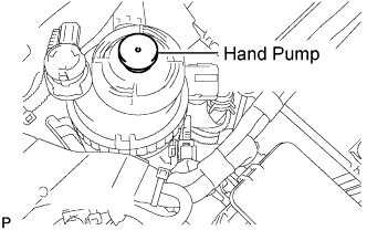
Using the hand pump mounted on the fuel filter cap, bleed air from the fuel system. Continue pumping until the pump resistance increases.
Note
-
Hand pump pumping speed: Max. 2 strokes/ sec.
-
The hand pump must be pushed with a full stroke during pumping.
-
When the fuel pressure at the supply pump inlet port reaches a saturated pressure, the hand pump resistance increases.
-
If pumping is interrupted during the air bleeding process, fuel in the fuel line may return to the fuel tank. Continue pumping until the hand pump resistance increases.
-
If the hand pump resistance does not increase despite consecutively pumping 200 times or more, there may be a fuel leak between the fuel tank and fuel filter, the hand pump may be malfunctioning, or the vehicle may have run out of fuel.
-
If air bleeding using the hand pump is incomplete, the common rail pressure does not rise to the pressure range necessary for normal use, and the engine cannot be started.
-
-
Check if the engine starts.
Note
-
Even if air bleeding using the hand pump has been completed, the starter may need to be cranked for 10 seconds or more to start the engine.
-
Do not crank the engine continuously for more than 20 seconds. The battery may be discharged.
-
Use a fully-charged battery.
-
When the engine can be started, proceed to the next step.
-
If the engine cannot be started, bleed air again using the hand pump until the hand pump resistance increases (refer to the procedures above). Then start the engine.
-
-
Turn the ignition switch off.
-
Connect the intelligent tester to the DLC3.
-
Turn the ignition switch to ON and turn the intelligent tester on.
-
Clear the DTCs.
-
w/ DPF: Click here
-
w/o DPF: Click here
-
-
Start the engine.*1
-
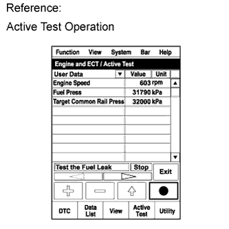
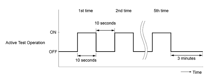
Enter the following menus: Powertrain / Engine and ECT / Active Test / Test the Fuel Leak.*2
-
Perform the following test 5 times with on/off intervals of 10 seconds: Active Test / Test the Fuel Leak.*3
-
Allow the engine to idle for 3 minutes or more after performing the Active Test for the fifth time.
Tech Tips
When the Active Test "Test the Fuel Leak" is used to change the pump control mode, the actual fuel pressure inside the common rail drops below the target fuel pressure when the Active Test is off, but this is normal and does not indicate a pump malfunction.
-
Enter the following menus: Powertrain / Engine and ECT / DTC.
-
Read Current DTCs.
-
Clear the DTCs.
-
w/ DPF: Click here
-
w/o DPF: Click here
Tech Tips
It is necessary to clear the DTCs as DTC P1604 or P1605 may be stored when air is bled from the fuel system after replacing or repairing fuel system parts.
-
-
Repeat steps *1 to *3.
-
Enter the following menus: Powertrain / Engine and ECT / DTC.
-
Read Current DTCs.
OK No DTCs are output.
-
-
INSPECT FOR FUEL LEAK
-
Perform the Active Test.
-
Connect the intelligent tester to the DLC3.
-
Turn the ignition switch to ON.
-
Turn the intelligent tester on.
-
Enter the following menus: Powertrain / ECD / Active Test.
-
Perform the Active Test.
Intelligent Tester Display Test Part Control Range Diagnostic Notes Test the Fuel Leak Pressurize common rail interior and check for fuel leaks Stop/Start
-
Fuel pressure inside common rail increased to specified value and engine speed increased to 2000 rpm when Active Test is performed
-
Above conditions preserved while Active Test is being performed
-
-
-
-
INSPECT FOR COOLANT LEAK
CAUTION:
Do not remove the radiator cap while the engine and radiator are still hot. Hot, pressurized engine coolant and steam may be released and cause serious burns.
-
Fill the radiator with coolant and attach a radiator cap tester to the radiator.
-
Warm up the engine.
-
Using a radiator cap tester, increase the pressure inside the radiator to 137 kPa (1.4 kgf/cm2, 19.9 psi), and check that the pressure does not drop.
Tech Tips
If the pressure drops, check the hoses, radiator and water pump for leaks. If no external leaks are found, check the heater core, cylinder block and cylinder head.
-
-
INSTALL ENGINE SERVICE HOLE SUB COVER SUB-ASSEMBLY
-
INSTALL FRONT SEAT ASSEMBLY RH
-
INSTALL FRONT DOOR SCUFF PLATE RH
-
PERFORM ELECTRIC EGR CONTROL VALVE COMPENSATION RESET