FUEL TANK INSTALLATION

-
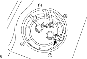
INSTALL FUEL PUMP ASSEMBLY
-
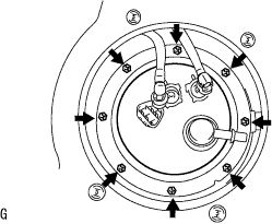
Install the fuel pump assembly and fuel bent tube set plat with the 8 bolts.
- Torque:
- 4.0 N*m { 41 kgf*cm, 35 in.*lbf }
-
-
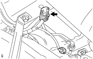
CONNECT FUEL TANK WIRE
-
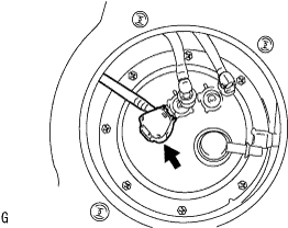
Connect the fuel tank wire connector to the fuel pump assembly.
-
-
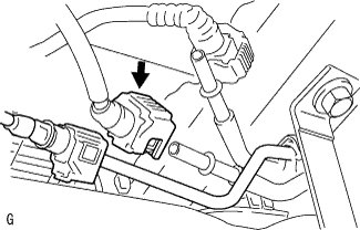
CONNECT FUEL TANK MAIN TUBE SUB-ASSEMBLY
-
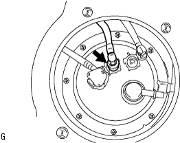
connect the fuel tank main tube with the tube joint clip.
-
-
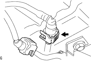
CONNECT FUEL TANK RETURN TUBE
-
Connect the fuel tank return tube with the tube joint clip.
-
-
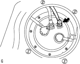
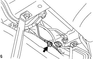
CONNECT FUEL EVAPORATION TUBE SUB-ASSEMBLY NO.1
-
Match the axis of the connector with the axis of the pipe, and push into the connector until the connector makes a 'click' sound. In case that the connection is tight, apply a small amount of fresh engine oil to the tip of the pipe.
Note
-
Check that there is any damage or foreign objects in the connected part of the pipe.
-
After finishing the connection, check if the pipe and the connector are securely connected by pulling them.
-
-
-
INSTALL FUEL TANK ASSEMBLY
-
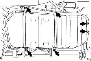
Using the transmission jack, install the 2 fuel tank band sub-assemblies and fuel tank assembly with the 6 bolts.
- Torque:
- 38 N*m { 398 kgf*cm, 28 ft.*lbf }
-
Connect the parking brake cable No.3 with the bolt.
- Torque:
- 15 N*m { 153 kgf*cm, 11 ft.*lbf }
-
-
CONNECT FUEL TANK HOSE NO.3
-
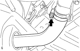
Connect the fuel hose No.3, and tighten the clamp bolt.
-
-
CONNECT FUEL TANK BREATHER TUBE SUB-ASSEMBLY NO.1
-
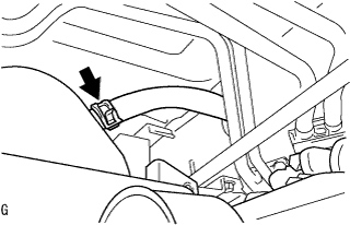
Connect the fuel tank breather tube and clip.
-
-
CONNECT FUEL TANK MAIN TUBE SUB-ASSEMBLY
-
Connect the fuel tank main tube sub-assembly and clamp. Click here
-
-
CONNECT FUEL TANK RETURN TUBE
-
Connect the fuel return tube sub-assembly. Click here
-
-
CONNECT FUEL EVAPORATION TUBE SUB-ASSEMBLY NO.1
-
Disconnect fuel evaporation tube sub-assembly. Click here
-
-
CONNECT FUEL TANK WIRE
-
Connect the fuel tank wire.
-
-
INSTALL PROPELLER SHAFT ASSEMBLY
Tech Tips
-
Propeller shaft assembly for Super Long Wheelbase Click here
-
Propeller shaft assembly for Long Wheelbase Click here
-
-
BLEED FUEL LINE
-
Check that the battery voltage is above 12 V.
-
Disconnect the negative terminal cable from the battery.
-
Disconnect the fuel hose from the fuel filter assembly.
-
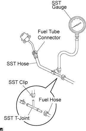
Install SST (pressure gauge) using SSTs and a fuel tube connector as shown in the illustration.
- SST
- 09268-41048 ( 09268-41120, 90467-13001, 95336-08070, 09268-41500 )
-
Wipe off any splattered gasoline.
-
Reconnect the negative terminal cable to the battery.
-
Connect the intelligent tester to the DLC3 (See step 1 in check fuel pump operation).
-
Measure the fuel pressure.
Fuel pressure 281 to 287 kPa (2.87 to 2.93 kgf/cm2, 40.8 to 41.7 psi) If pressure is high, replace the fuel pressure regulator.
If pressure is low, check the fuel hoses, fuel hose connection, fuel pump, fuel filter and fuel pressure regulator.
-
Disconnect the intelligent tester from the DLC3.
-
Stop the engine.
-
Measure the fuel pressure at idle.
Fuel pressure 281 to 287 kPa (2.87 to 2.93 kgf/cm2, 40.8 to 41.7 psi) If pressure is not as specified, check the vacuum sensing hose and fuel pressure regulator.
-
Stop the engine.
-
Check that the fuel pressure remains as specified for 5 minutes after the engine has stopped.
Fuel pressure 147 kPa (1.5 kgf/cm2, 21 psi) or higher If pressure is not as specified, check the fuel pump, pressure regulator and/or injector.
-
After checking fuel pressure, disconnect the negative terminal cable from the battery and carefully remove the SST to prevent gasoline from splashing.
-
Connect the fuel hose to the fuel filter assembly.
-
Reconnect the negative terminal cable to the battery.
-
Check for fuel leakage.
-
-
CHECK FOR FUEL LEAKS
-
When using the intelligent tester
-
Connect the intelligent tester to the DLC3.
-
Turn the ignition switch to the on position and intelligent tester main switch ON.
Note
Do not start the engine.
-
Select the Active Test mode on the intelligent tester.
Tech Tips
Please refer to the intelligent tester operator's manual for further details.
-
-
When not using the intelligent tester.
-
Disconnect the fuel pump connector.
-
Using a service wire, connect terminals FP and +B of the relay block.
Note
Pay attention to the terminal connecting position to avoid a malfunction.
-
Turn the ignition switch to the ON position, and check that the fuel pump operates.
Note
Do not start the engine.
-
-
Check that there are no fuel leaks anywhere on the fuel system after doing maintenance.
-
Check that the pulsation damper screw rises up when the fuel pump operates.
If operation is not as specified, check the following parts:
-
Fusible link
-
Fuel pump
-
Wiring connections
-
ECM
-
Fuses
-
-
Turn the ignition switch off.
-
Disconnect the intelligent tester from the DLC3.
-