EXHAUST FUEL ADDITION INJECTOR (for DPF) INSTALLATION

-
INSTALL EXHAUST FUEL ADDITION INJECTOR ASSEMBLY
Note
If there is foreign matter on the installation surface of the exhaust fuel addition injector, be sure to clean the injector before installation.
-
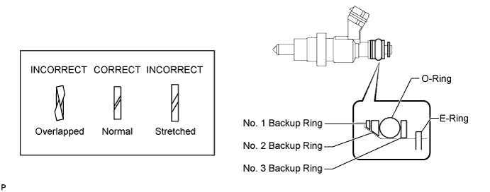
Install a new E-ring, a new O-ring and 3 new backup rings to the exhaust fuel addition injector.
Note
-
Check that there is no foreign matter or damaged areas in the injector O-ring groove.
-
Check that the No. 1 and No. 2 backup rings are installed in the correct direction.
-
Make sure that the backup rings and O-ring are installed in the correct order.
-
Check that the alignment openings of the backup rings are not stretched and that the ends of the backup rings are not overlapped as shown in the illustration.
-
After installing the O-ring, check that it is not contaminated with foreign matter and is not damaged.
-
-
Install a new gasket and the exhaust fuel addition injector.
-
Using a T40 "TORX" socket wrench, install the No. 1 nozzle holder clamp with the screw.
- Torque:
- 10 N*m { 102 kgf*cm, 7 ft.*lbf }
-
Install the injector holder with the 2 bolts.
- Torque:
- 28 N*m { 286 kgf*cm, 21 ft.*lbf }
-
-
INSTALL TURBINE OUTLET ELBOW
-
CONNECT CABLE TO NEGATIVE BATTERY TERMINAL
Note
When disconnecting the cable, some systems need to be initialized after the cable is reconnected Click here.
-
ADD ENGINE COOLANT
-
Firmly tighten the drain plugs.
-
Fill the radiator reservoir assembly with engine coolant to the top of the inlet.
Standard Capacity Item Specified Condition w/o Heater 13.2 liters (13.9 US qts, 11.6 Imp. qts) w/ Front Heater 14.2 liters (15.0 US qts, 12.5 Imp. qts) w/ Front and Rear Heaters 16.2 liters (17.1 US qts, 14.3 Imp. qts) Note
Do not substitute plain water for engine coolant.
Tech Tips
-
Use of improper coolants may damage the engine cooling system.
-
Use only Toyota Super Long Life Coolant or similar high quality ethylene glycol based non-silicate, non-amine, non-nitrite, and non-borate coolant with long-life hybrid organic acid technology (coolant with long-life hybrid organic acid technology consists of a combination of low phosphates and organic acids).
-
-
Loosen the bleeder plug of the outlet housing.
-
When air is bled and the engine coolant drains out, firmly tighten the bleeder plug.
- Torque:
- 8.0 N*m { 82 kgf*cm, 71 in.*lbf }
-

Add engine coolant up to the B line mark in the radiator reservoir assembly and install the radiator reservoir cap sub-assembly.
-
Warm up the engine until the thermostat opens.
-
While the thermostat is open, circulate the engine coolant for several minutes.
Tech Tips
The thermostat open timing can be confirmed by pressing the No. 3 radiator hose by hand, and checking when the engine coolant starts to flow inside the hose.
-
-

After the engine cools down, check that the engine coolant level is between the LOW and FULL level marks.
-
-
INSPECT FOR COOLANT LEAK
CAUTION:
Do not remove the radiator cap while the engine and radiator are still hot. Hot, pressurized engine coolant and steam may be released and cause serious burns.
-
Fill the radiator with coolant and attach a radiator cap tester to the radiator.
-
Warm up the engine.
-
Using a radiator cap tester, increase the pressure inside the radiator to 137 kPa (1.4 kgf/cm2, 19.9 psi), and check that the pressure does not drop.
Tech Tips
If the pressure drops, check the hoses, radiator and water pump for leaks. If no external leaks are found, check the heater core, cylinder block and cylinder head.
-
-
INSPECT FOR FUEL LEAK
-
Perform the Active Test.
-
Connect the GTS to the DLC3.
-
Turn the ignition switch to ON.
-
Turn the GTS on.
-
Enter the following menus: Powertrain / Engine and ECT / Active Test.
-
Perform the Active Test.
Tester Display Test Part Control Range Diagnostic Notes Test the Fuel Leak Pressurize common rail interior and check for fuel leaks Stop/Start
-
Fuel pressure inside common rail increased to specified value and engine speed increased to 2000 rpm when Active Test is performed
-
Above conditions preserved while Active Test is being performed
-
-
-