FUEL INJECTION PUMP INSTALLATION

-
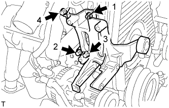
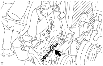
INSTALL INJECTION OR SUPPLY PUMP ASSEMBLY
-
Install the injection or supply pump assembly to timing gear case, and temporarily tighten the 2 nuts.
-
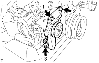
Install injection pump stay No.1 to the injection or supply pump assembly rear end, and temporarily tighten the 3 bolts.
-
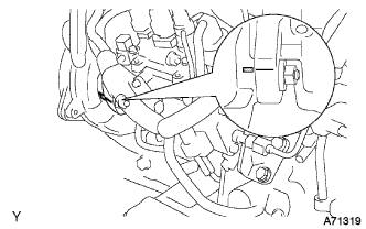
Rotate the pump body to make the marking of pump flange conform to the making of timing of gear case.
-
Tighten the 2 nuts to install the injection or supply pump assembly.
- Torque:
- 21 N*m { 210 kgf*cm, 15 ft.*lbf }
-
Tighten the 3 bolts to install the injection pump stay No.1.
- Torque:
- Injection pump stay No.1 x Cylinder Block
- 21 N*m { 210 kgf*cm, 15 ft.*lbf }
- Injection pump stay No.1 x Injection Pump
- 18 N*m { 185 kgf*cm, 13 ft.*lbf }
-
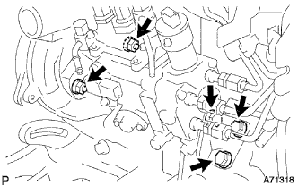
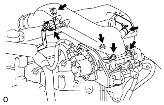
Connect the 3 fuel hoses.
-
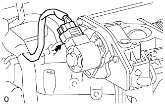
Connect the engine speed sensor connector.
-
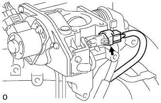
Connect the spill control valve connector.
-
Connect the correction unit connector.
-
Connect the timer control valve connector.
-
Connect the fuel temperature sensor connector.
-
Connect the engine wire clamp.
-
-
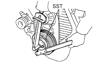
INSTALL INJECTION PUMP DRIVE PULLEY
-
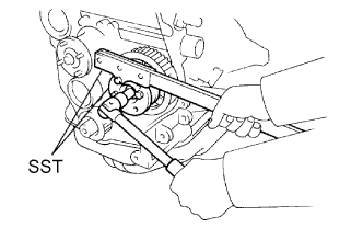
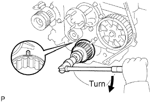
Using SST, install the injection pump drive pulley with the nut.
- SST
- 09213-14010 ( 91651-60865 )
- 09330-00021
- Torque:
- 64 N*m { 650 kgf*cm, 47 ft.*lbf }
-
-
INSTALL INJECTION PIPE SET
-
Connect the 2 lower clamps on the intake manifold.
-
Install the 4 injection pipes.
- Torque:
- 25 N*m { 250 kgf*cm, 18 ft.*lbf }
-
Secure the injection pipes with the 2 upper pipe clamps and 2 nuts.
- Torque:
- 5.0 N*m { 50 kgf*cm, 44 in.*lbf }
-
-
INSTALL VENTURI ASSEMBLY
-
Install a new gasket and venturi.
-
Connect the throttle control motor connector.
-
Connect the throttle open switch connector.
-
-
INSTALL INTAKE AIR CONNECTOR SUB-ASSEMBLY
-
Install a new gasket and intake air connector with the bolt and 3 nuts.
- Torque:
- bolt
- 18 N*m { 184 kgf*cm, 13 ft.*lbf }
- Nut
- 12 N*m { 122 kgf*cm, 9 ft.*lbf }
-
Connect the turbo pressure sensor connector.
-
Connect the ventilation hose.
-
-
INSTALL AIR CLEANER HOSE NO.2
-
Install the air cleaner hose No.2 with the clamp.
-
-
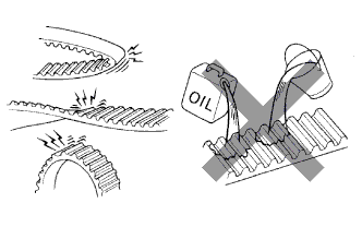
INSPECT TIMING BELT
Note
-
Do not bend, twist or turn the timing belt inside out.
-
Do not allow the timing belt to come into contact with oil, water or steam.
-
Do not utilize timing belt tension when installing or removing the mount bolt of the camshaft timing pulley.
If there are any defects as shown in the illustrations, check the following points:
-
If there is premature parting:
-
Check for proper installation.
-
Check the timing cover gasket for damage and proper installation.
-
-
If the belt teeth are cracked or damaged, check if either camshaft is locked.
-
If there is noticeable wear or cracks on the belt face, check if there are nicks on the side of the idler pulley lock and water pump.
-
If there is wear or damage to only one side of the belt, check the belt guide and the alignment of each pulley.
-
If there is noticeable wear on the belt teeth:
-
Check the timing cover for damage.
-
Check that the gasket has been installed correctly.
-
Check for foreign matter on the pulley teeth.
If necessary, replace the timing belt.
-
-
-
INSPECT TIMING BELT IDLER SUB-ASSEMBLY
-
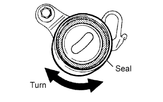
Visually check the seal portion of the timing belt idler No.1 for oil leakage.
If leakage is found, replace the timing belt idler No.1.
-
Check that the timing belt idler No.1 turns smoothly.
If necessary, replace the timing belt idler No.1.
-
-
INSPECT IDLER TENSION SPRING
-
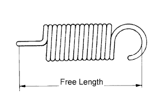
Measure the free length of the tension spring.
Free length 44.4 to 45.4 mm (1.748 to 1.787 in.) If the free length is not as specified, replace the tension spring.
-
Measure the tension of the tension spring at the specified installed length.
Installed tension 53 to 59 N (5.42 to 5.98 kgf, 11.9 to 13.2 lbf) at 52.1 mm (2.051 in.)
-
-
INSPECT WATER PUMP ASSEMBLY
-
Remove the 6 bolts and tension spring bracket.
-
Remove the water pump and gasket.
-
-
SET NO.1 CYLINDER TO TDC/COMPRESSION
-
Using the crankshaft pulley bolt, align its groove with the timing pointer by turning the crankshaft clockwise.
Note
Do not turn the crankshaft pulley counterclockwise.
-
Set the timing and drive pulleys at each position.
Note
-
The engine should be cold.
-
When turning the crankshaft or camshaft, the valve heads will hit against the piston top. Do not turn them more than necessary.
-
-
-
INSTALL TIMING BELT
Tech Tips
If reusing the timing belt, align the points marked during removal, and install the timing belt with the arrow pointing in the direction of engine revolution.
-
Remove any oil or water on each pulleys, and keep them clean.
-
Install the timing belt on the crankshaft timing pulley and timing belt idlers.
-
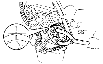
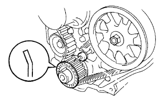
Using SST, slightly turn the injection pump drive pulley clockwise. Hang the timing belt on the pulley, and align the timing marks of the drive pulley and timing belt case.
- SST
- 09960-10010 ( 09962-01000, 09963-01000 )
-
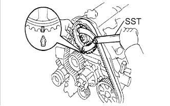
Using SST, slightly turn the camshaft timing pulley clockwise. Hang the timing belt on the timing pulley, and align the timing marks of the timing pulley and timing belt case.
- SST
- 09960-10010 ( 09962-01000, 09963-01000 )
-
Check that the timing belt has tension between the injection pump drive and camshaft timing pulleys.
-
Install the timing belt on the timing belt idler No.2.
-
-
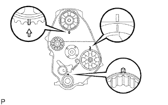
CHECK VALVE TIMING
-
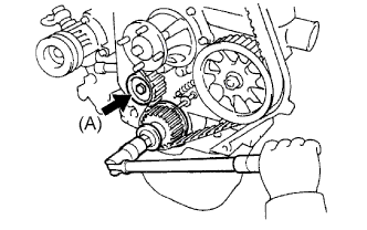
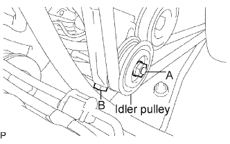
Loosen the timing belt idler No.1 bolt (A), and stretch the timing belt.
-
Slowly turn the crankshaft pulley 2 revolutions from TDC to TDC.
Note
Always turn the crankshaft clockwise.
-
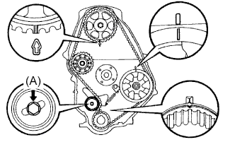
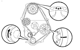
Check each pulley aligns with the timing marks as shown in the illustration.
If the timing marks do not align, remove the timing belt and reinstall it.
-
Tighten the timing belt idler No.1 bolt (A).
- Torque:
- 44 N*m { 450 kgf*cm, 33 ft.*lbf }
-
-
INSTALL TIMING BELT GUIDE
-
Install the belt guide with the cup side facing outward.
-
-
INSTALL TIMING CHAIN OR BELT COVER SUB-ASSEMBLY
-
Remove the 2 nuts and wire harness clamp bracket.
-
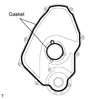
Install the 2 gaskets to the timing belt cover.
-
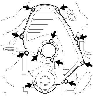
Install the timing belt cover with the 11 bolts.
- Torque:
- 11 N*m { 105 kgf*cm, 8 ft.*lbf }
-
Install the 2 nuts and wire harness clamp bracket.
-
-
INSTALL CRANKSHAFT PULLEY
-
Align the pulley set key with the key groove of the pulley, and slide the pulley to the crankshaft.
-
Using SST, install the new pulley bolt.
- SST
- 09213-54015 ( 91651-60855 )
- 09330-00021
- Torque:
- 235 N*m { 2,400 kgf*cm, 173 ft.*lbf }
-
-
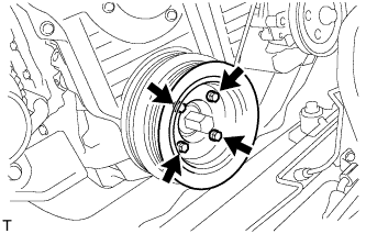
INSTALL VANE PUMP DRIVE PULLEY
-
w/o Air conditioning:
-
Install the vane pump drive pulley and vane pump pulley spacer with the 4 bolts.
- Torque:
- 19 N*m { 195 kgf*cm, 14 ft.*lbf }
-
-
w/ Air conditioning:
-
Install the 2 vane pump drive pulleys with the 4 bolts.
- Torque:
- 18 N*m { 184 kgf*cm, 13 ft.*lbf }
-
-
-
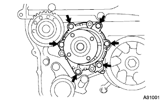
INSTALL COMPRESSOR MOUNTING BRACKET (W/ AIR CONDITIONING)
-
Temporarily install the compressor mounting bracket with the 4 bolts.
-
Using several steps, uniformly install and tighten the 4 bolts in the sequence shown in the illustration.
- Torque:
- 85 N*m { 870 kgf*cm, 63 ft.*lbf }
-
Temporarily tighten the bolt and spacer.
-
Temporarily install the compressor mounting bracket with the 3 bolts.
-
Using several steps, uniformly install and tighten the 3 bolts in the sequence shown in the illustration.
- Torque:
- 47 N*m { 475 kgf*cm, 36 ft.*lbf }
-
-
INSTALL COMPRESSOR AND MAGNETIC CLUTCH (W/ AIR CONDITIONING)
-
TEMPORARILY TIGHTEN FAN PULLEY
-
Temporarily tighten the fan pulley with the 4 bolts.
-
-
INSTALL FAN & GENERATOR V BELT (W/O AIR CONDITIONING)
-
Install the V belt.
-
Using a bar, adjust the tension of the V belt.
-
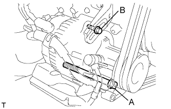
Tighten the bolts A and B.
- Torque:
- Bolt A
- 75 N*m { 765 kgf*cm, 55 ft.*lbf }
- Bolt B
- 18 N*m { 185 kgf*cm, 13 ft.*lbf }
-
Check the tension of the V belt. Click here
-
-
INSTALL FAN & GENERATOR V BELT (W/ AIR CONDITIONING)
-
Install the V belt.
-
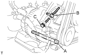
Tightening the bolt C, adjust the tension of the V belt.
-
Tighten the bolts A and B.
- Torque:
- Bolt A
- 75 N*m { 765 kgf*cm, 55 ft.*lbf }
- Bolt B
- 18 N*m { 185 kgf*cm, 13 ft.*lbf }
-
Check the tension of the V belt. Click here
-
-
TIGHTEN FAN PULLEY
-
Install the 4 nuts, fan spacer and fan pulley.
- Torque:
- 19 N*m { 185 kgf*cm, 14 ft.*lbf }
-
-
INSTALL V (COOLER COMPRESSOR TO CRANKSHAFT PULLEY) BELT NO.1 (W/ AIR CONDITIONING)
-
Install the V belt.
-
Tightening the bolt B, adjust the tension of the V belt.
-
Tighten nut A.
- Torque:
- 39 N*m { 400 kgf*cm, 29 ft.*lbf }
-
Check the tension of the V belt. Click here
-
-
INSTALL VANE PUMP V BELT
-

Install the V belt.
-
Using a bar, adjust the tension of the V-ribbed belt.
-
Tighten the bolt A and nut B.
- Torque:
- Bolt (A)
- 48 N*m { 489 kgf*cm, 35 ft.*lbf }
- Nut (B)
- 64 N*m { 635 kgf*cm, 47 ft.*lbf }
-
Check the tension of the V belt. Click here
-
-
ADD ENGINE COOLANT
-
Fill the radiator reservoir assembly with coolant to the top of the inlet.
Standard Capacity Item Specified Condition w/o Heater 12.3 liters (13.0 US qts, 10.8 Imp. qts) w/ Front Heater 13.3 liters (14.1 US qts, 11.7 Imp. qts) w/ Front and Rear Heaters 15.3 liters (16.2 US qts, 13.5 Imp. qts) Note
Do not substitute plain water for engine coolant.
Tech Tips
-
Use of improper coolants may damage the engine cooling system.
-
Use only Toyota Super Long Life Coolant or similar high quality ethylene glycol based non-silicate, non-amine, non-nitrite, and non-borate coolant with long-life hybrid organic acid technology (coolant with long-life hybrid organic acid technology consists of a combination of low phosphates and organic acids).
-
-

Add coolant up to the B line mark in the radiator reservoir assembly and install the reservoir cap.
-
Warm up the engine until the thermostat opens.
-
While the thermostat is open, circulate the coolant for several minutes.
Tech Tips
The thermostat open timing can be confirmed by pressing the inlet radiator hose by hand, and checking when the engine coolant starts to flow inside the hose.
-
-

After the engine cools down, check that the coolant level is between the LOW and FULL level marks.
-
-
CHECK FOR ENGINE COOLANT LEAKS
-
Check that the engine coolant level is between the LOW and FULL lines when the engine is cold. If the engine coolant is low, check for leaks and add "TOYOTA Super Long Life Coolant (SLLC)" or similar high quality ethylene glycol based non-silicate, non-amine, non-nitrite and non-borate coolant with long-life hybrid organic acid technology to the FULL line.
Note
Do not substitute plain water for engine coolant.
-
-
CHECK FOR FUEL LEAKS
-
Check that there are no fuel leaks anywhere on the fuel system after doing maintenance.
Tech Tips
When checking for fuel leaks, make sure that there is pressure in the fuel line.
-