FUEL PUMP REMOVAL

-
DISCONNECT BATTERY NEGATIVE CABLE
-
REMOVE FRONT SEAT ASSEMBLY RH (for Hi-back Seat Type)
-
Perform the same procedure as above on the opposite side. Click here
-
-
REMOVE FRONT SEAT ASSEMBLY RH (for Low-back Seat Type)
-
Perform the same procedure as above on the opposite side. Click here
-
-
REMOVE FRONT DOOR SCUFF PLATE RH
-
REMOVE ENGINE SERVICE HOLE SUB COVER SUB-ASSEMBLY
-
Roll up the carpet, and remove the engine service hole sub cover assembly.
-
-
REMOVE FAN & GENERATOR V BELT
-
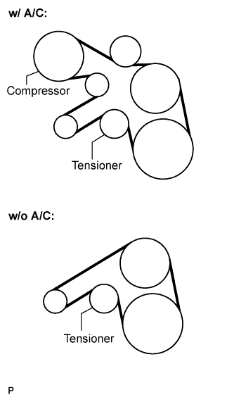
Remove the drive belt by rotating the tensioner pulley in clockwise direction to loosen its tension with the pulley set bolt of the tensioner.
-
-
REMOVE TIMING BELT COVER NO.1
-
Remove the wire harness clamp.
-
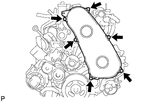
Remove the 6 bolts and timing belt cover No.1.
-
-
REMOVE TIMING BELT
-
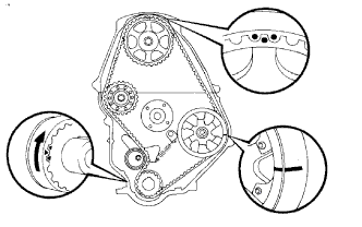
Remove the timing belt.
Tech Tips
If reusing the timing belt, draw a direction arrow on the timing belt (in the direction of engine revolution), and place matchmarks on the pulleys and timing belt.
-
Turn the crankshaft 90° counterclockwise, and put the timing mark of the crankshaft timing pulley with the protrusion of the timing gear case.
Note
If the timing belt is disengaged, having the crankshaft timing pulley at the wrong angle can cause the piston head and valve head to come into contact with each other when you remove the camshaft timing pulley, causing damage. So always set the crankshaft pulley at the correct angle.
-
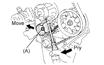
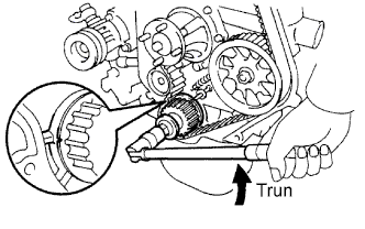
Loosen the timing belt idler No.1 bolt (A), and shift the idler to the left as far as possible.
-
Temporarily tighten the pulley bolt (A), and then relieve the timing belt tension.
-
Remove the timing belt.
-
-
DISCONNECT VANE PUMP OIL RESERVOIR ASSEMBLY
-
Remove the 2 bolts and vane pump oil reservoir assembly.
Note
Suspend the vane pump oil reservoir assembly with wire to prevent power steering fluid from spilling out.
-
-
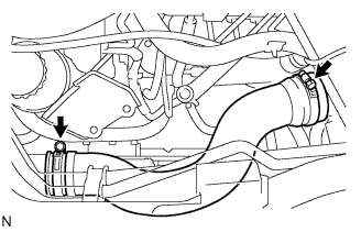
DISCONNECT OIL RETURN HOSE (w/ Inter Cooler)
-
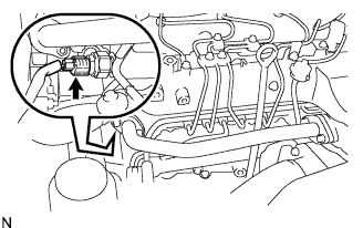
Disconnect the oil return hose from the intake manifold.
-
-
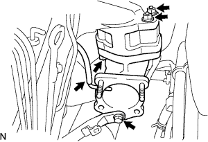
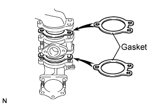
REMOVE EGR PIPE SUB-ASSEMBLY NO.1 (w/ EGR Valve)
-
Disconnect the fuel pressure sensor connector.
-
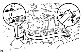
Remove the 2 bolts, 2 nuts, and the EGR pipe sub-assembly.
-
Remove the 2 gaskets.
-
-
REMOVE AIR HOSE NO.4
-
Loosen the 2 clamps.
-
Remove the air hose No.4.
-
-
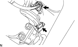
REMOVE DIESEL THROTTLE BODY ASSEMBLY
-
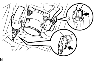
Disconnect the 2 throttle body connectors.
-
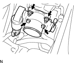
Remove the 2 bolts, 2 nuts, and the diesel throttle body assembly.
-
Remove the gasket from intake air connector.
-
-
REMOVE ENGINE SERVICE HOLE COVER NO.2
-
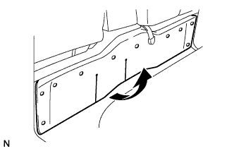
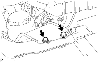
Roll up the carpet.
-
Remove the 3 bolts and the engine service hole cover No.2.
-
-
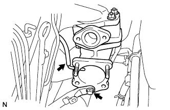
REMOVE INTAKE AIR CONNECTOR (w/o EGR Valve)
-
Remove the bolt, and separate the manifold stay.
-
Disconnect the vacuum hose from intake air connector.
-
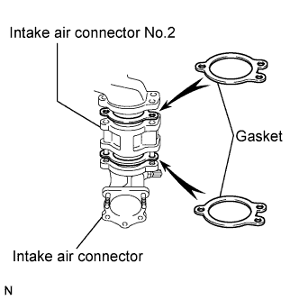
Remove the bolt, 2 nuts and the intake air connector assembly.
-
Remove the 2 gaskets and intake air connector No.2 from the intake air connector.
-
-
REMOVE ELECTRIC EGR CONTROL VALVE ASSEMBLY (w/ EGR Valve)
-
Remove the vacuum regulating valve.
-

Remove the 2 vacuum hoses and the vacuum regulating valve connector.
-
Remove the 2 bolts and the vacuum regulating valve.
-
-
Remove the EGR valve assembly with the sensor.
-
Remove the bolt, and separate the manifold stay.
-
Disconnect the vacuum hose from the intake air connector.
-
Disconnect the intake air temperature sensor connector.
-
Disconnect the EGR valve position sensor connector.
-
Remove the bolt, 2 nuts and the intake air connector assembly.
-
Remove the 2 gaskets and EGR valve assembly from the intake air connector.
-
-
-
REMOVE OIL LEVEL GAGE GUIDE
-
Remove the oil level gauge.
-
Remove the bolt and oil level gauge guide.
-
-
REMOVE INJECTION PIPE
- SST
- 09023-12701
-
Remove the injection pipe.
-
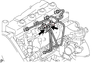
Remove the 2 nuts and injection pipe clamp No.3.
-
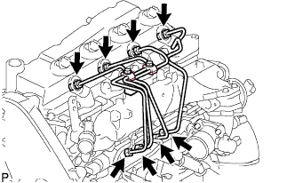
Using SST, remove the 4 injection pipes.
- SST
- 09023-12701
-
-
REMOVE FUEL INLET PIPE SUB-ASSEMBLY
-
Using SST, remove the fuel inlet pipe sub-assembly.
- SST
- 09023-12701
-
-
REMOVE INJECTION OR SUPPLY PUMP ASSEMBLY
-
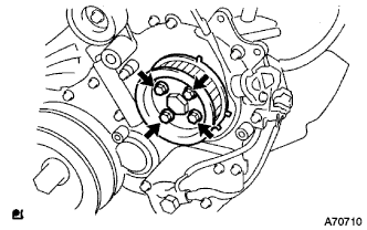
Remove the 4 bolts.
-
Remove the camshaft timing pulley flange No.2 and pump drive shaft pulley.
-
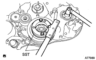
Using SST, remove the supply pump gear set nut and O-ring while holding the crankshaft pulley.
- SST
- 09213-58013
- 09330-00021
-
Disconnect the 2 fuel hoses.
-
Disconnect the 2 connectors and wire harness.
-
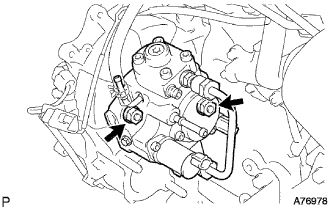
Loosen the 2 nuts as shown in the illustration.
-
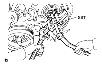
Using SST, disengage the supply pump from the supply pump gear.
- SST
- 09950-50013 ( 09951-05010, 09952-05010, 09953-05020, 09954-05021 )
-
Remove the 2 nuts and supply pump from the engine.
-
Remove the O-ring from the supply pump.
-
Remove the pulley key from the supply pump.
-