FUEL INJECTOR REMOVAL

-
DISCHARGE FUEL SYSTEM PRESSURE
-
Check that the battery voltage is above 12 V.
-
Disconnect the negative terminal cable from the battery.
-
Disconnect the fuel hose from the fuel filter assembly.
-
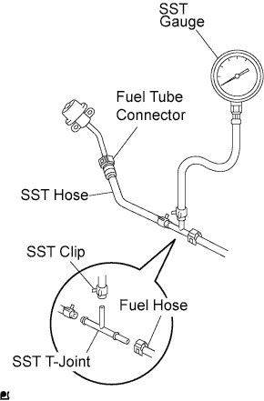
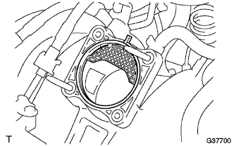
Install SST (pressure gauge) using SSTs and a fuel tube connector as shown in the illustration.
- SST
- 09268-41048 ( 09268-41120, 90467-13001, 95336-08070, 09268-41500 )
-
Wipe off any splattered gasoline.
-
Reconnect the negative terminal cable to the battery.
-
Connect the intelligent tester to the DLC3 (See step 1 in check fuel pump operation).
-
Measure the fuel pressure.
Fuel pressure 281 to 287 kPa (2.87 to 2.93 kgf/cm2, 40.8 to 41.7 psi) If pressure is high, replace the fuel pressure regulator.
If pressure is low, check the fuel hoses, fuel hose connection, fuel pump, fuel filter and fuel pressure regulator.
-
Disconnect the intelligent tester from the DLC3.
-
Stop the engine.
-
Measure the fuel pressure at idle.
Fuel pressure 281 to 287 kPa (2.87 to 2.93 kgf/cm2, 40.8 to 41.7 psi) If pressure is not as specified, check the vacuum sensing hose and fuel pressure regulator.
-
Stop the engine.
-
Check that the fuel pressure remains as specified for 5 minutes after the engine has stopped.
Fuel pressure 147 kPa (1.5 kgf/cm2, 21 psi) or higher If pressure is not as specified, check the fuel pump, pressure regulator and/or injector.
-
After checking fuel pressure, disconnect the negative terminal cable from the battery and carefully remove the SST to prevent gasoline from splashing.
-
Connect the fuel hose to the fuel filter assembly.
-
Reconnect the negative terminal cable to the battery.
-
Check for fuel leakage.
-
-
DISCONNECT BATTERY NEGATIVE CABLE
-
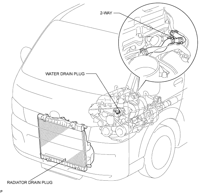
DRAIN ENGINE COOLANT
CAUTION:
Do not remove the radiator cap while the engine and radiator are still hot. Pressurized, hot engine coolant and steam may be released and cause serious burns.
-
Remove the radiator cap.
-
Loosen the radiator drain plug and a cylinder block drain plug. Then drain the coolant.
-
-
REMOVE FRONT SEAT ASSEMBLY RH (for Hi-back Seat Type)
Tech Tips
Use the same procedures described for the LH side. Click here
-
REMOVE FRONT SEAT ASSEMBLY RH (for Low-back Seat Type)
Tech Tips
Use the same procedures described for the LH side. Click here
-
REMOVE FRONT DOOR SCUFF PLATE RH
-
REMOVE ENGINE SERVICE HOLE SUB COVER SUB-ASSEMBLY
-
Roll up the carpet, and remove the 5 bolts and engine service hole sub cover.
-
-
REMOVE INTAKE AIR CONNECTOR
-
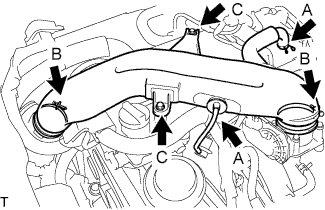
Slide the clamp and disconnect the No. 2 ventilation hose and vacuum hose. (A)
-
Loosen the 2 hose clamp bolts. (B)
-
Remove the 2 bolts and intake air connector. (C)
-
-
REMOVE THROTTLE BODY ASSEMBLY
-
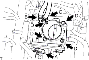
Disconnect the throttle motor connector. (A)
-
Slide the clamp and disconnect the water by-pass hose. (B)
-
Slide the clamp and disconnect the No. 2 water by-pass hose. (C)
-
for Type A:
Remove the 2 bolts and 2 nuts, and then remove the throttle body assembly. (D)
-
for Type B:
Remove the 4 bolts and throttle body assembly. (D)
-
Remove the gasket from the intake manifold.
-
-
DISCONNECT FUEL HOSE
-
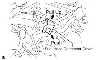
Pull the fuel hose connector cover up to release the lock. Click here
-
Disengage the fuel connector to disconnect the fuel hose. Click here
-
-
REMOVE FUEL DELIVERY PIPE SUB-ASSEMBLY
Note
Be careful not to drop the injectors when removing the delivery pipe.
-
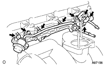
Disconnect the fuel hoses.
-
Disconnect the 4 injector connectors.
-
Remove the 2 bolts O-ring and fuel pulsation damper assembly.
-
Remove the 2 bolts and delivery pipe together with the 4 injectors.
-
Remove the delivery pipe spacers.
-
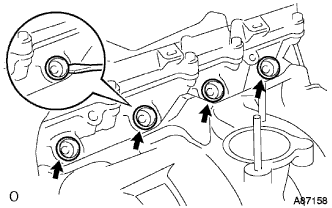
Using a screwdriver, pry out the 4 spacers from the cylinder head.
-
-
REMOVE INJECTOR ASSEMBLY
-
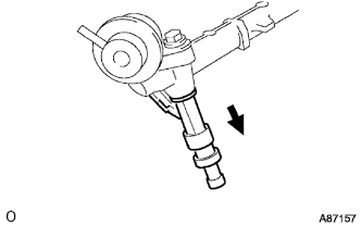
Pull out the 4 injectors from the delivery pipe.
-
Remove the O-rings from the injectors.
-