WINDOW DEFOGGER SYSTEM TERMINALS OF ECU

-
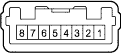
INSPECT HEATER CONTROL NOB NO.2 (DEFOGGER SWITCH)
-
Measure the voltage and resistance of each terminal of the connectors.
Symbols (Terminal No.) Wiring Color Terminal Description Condition Specified Condition E (1) - Body ground P - BR Ground for main power supply Always Below 1 Ω RrDEF (2) - E (1) L - BR Defogger signal Ignition switch ON, Defogger switch OFF → ON 10 to 14 V → Below 1 V IG (3) - E (1) L - BR Power supply (IG) Ignition switch ON 10 to 14 V If the result is not as specified, the defogger switch may have a malfunction.
-
-
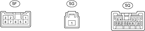
INSPECT INSTRUMENT PANEL JUNCTION BLOCK
-
Measure the voltage and resistance of each terminal of the connectors.
Symbols (Terminal No.) Wiring Color Terminal Description Condition Specified Condition DEF (5F-2) - Body ground B - Body ground Defogger signal Ignition switch ON, Defogger switch OFF → ON Below 1 V → 10 to 14 V +B (5G-1) - Body ground B-G - Body ground Main power supply (+B) Always 10 to 14 V DEFSW1 (5Q-4) - Body ground L-R - Body ground Main power supply (IG) Ignition switch ON 10 to 14 V DEFSW2 (5Q-12) - Body ground P-B - Body ground Defogger signal Ignition switch ON 10 to 14 V If the result is not as specified, the instrument panel junction block may have a malfunction.
-