POWER WINDOW CONTROL SYSTEM TERMINALS OF ECU

-
POWER WINDOW MASTER SWITCH

-
Disconnect the K5 (L5) switch with the K5 (L5) switch connector still connected.
-
Measure the voltage according to the value(s) in the table below.
-
Disconnect the K5 (L5) switch connector.
-
Measure the voltage and resistance according to the value(s) in the table below.
If the result is not as specified, there may be a malfunction on the wire harness side.
-
-
POWER WINDOW SWITCH

-
Disconnect the L6 (K6) switch with the L6 (K6) switch connector still connected.
-
Measure the voltage according to the value(s) in the table below.
-
-
INSTRUMENT PANEL J/B
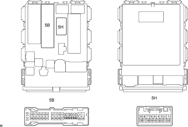
Standard voltage Symbols (Terminal No.) Wiring Color Terminal Description Condition Specified Condition B (5B-36) - Body ground W-L - Body ground +B (B) power supply Ignition switch ON 10 to 14 V BW (5H-1) - Body ground W-R - Body ground +B (BW) power supply Always 10 to 14 V