CLEARANCE WARNING INDICATOR INSPECTION

-
INSPECT CLEARANCE WARNING INDICATOR
-
Indicator check
-
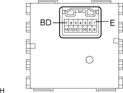
Connect the positive battery terminal to connector terminal 7 (BD), and the negative battery terminal to terminal 1 (E).
-
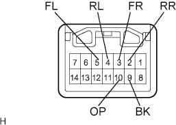
When the negative battery terminal is connected to each terminal of the connector as shown in the table, check that the corresponding LED comes on.
Standard The corresponding LED comes on Terminal LED Terminal to which negative battery terminal is connected Power indicator OP Back sonar BK Right front clearance sonar FR Left front clearance sonar FL Right rear clearance sonar RR Left rear clearance sonar RL If the result is not as specified, replace the clearance warning indicator.
-
-
Back and clearance sonar buzzer operation check
-
Connect the positive battery terminal to connector terminal 7 (BD), and the negative battery terminal to terminal 1 (E).
-
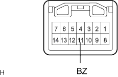
Connect the negative battery terminal to connector terminal 11 (BZ) and check the operation of the buzzer in the clearance warning indicator.
Standard Operating noise (clicking sounds) can be heard. If the result is not as specified, replace the clearance warning indicator.
Tech Tips
The clearance warning buzzer is separately excited, and will not sound unless an alternating voltage is applied.
-
-