CLEARANCE SONAR SYSTEM Indicator Circuit
DESCRIPTION
The indicator displays the location of the obstacle and the approximate distance between the vehicle and the obstacle either by blinking or turning on.
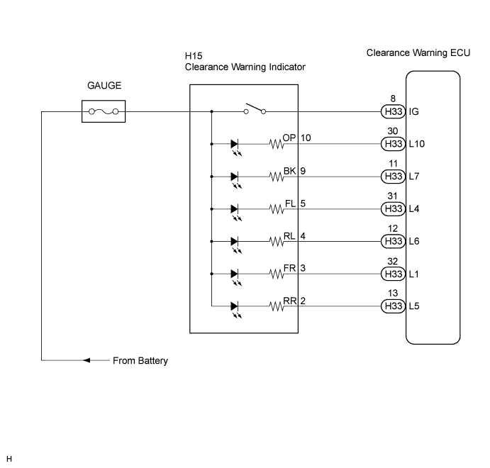
WIRING DIAGRAM
INSPECTION PROCEDURE
PROCEDURE
-
CHECK HARNESS AND CONNECTOR (CLEARANCE WARNING ECU - CLEARANCE WARNING INDICATOR)
-
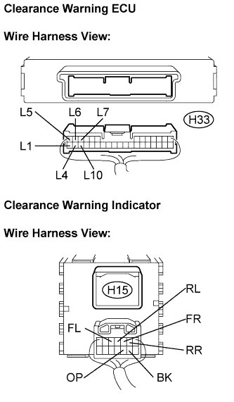
Disconnect the H33 connector from the clearance warning ECU.
-
Disconnect the H15 connector from the clearance warning indicator.
-
Measure the resistance according to the value(s) in the table below.
Resistance Tester connection
(Symbols)
Condition Specified condition H15-10 (OP) -
H33-30 (L10)
Always Below 1 Ω H15-9 (BK) - H33-11 (L7) Always Below 1 Ω H15-5 (FL) - H33-31 (L4) Always Below 1 Ω H15-4 (RL) - H33-12 (L6) Always Below 1 Ω H15-3 (FR) - H33-32 (L1) Always Below 1 Ω H15-2 (RR) - H33-13 (L5) Always Below 1 Ω H15-10 (OP) -
Body ground
Always 10 kΩ or higher H15-9 (BK) -
Body ground
Always 10 kΩ or higher H15-5 (FL) -
Body ground
Always 10 kΩ or higher H15-4 (RL) -
Body ground
Always 10 kΩ or higher H15-3 (FR) -
Body ground
Always 10 kΩ or higher H15-2 (RR) -
Body ground
Always 10 kΩ or higher
NG 
REPAIR OR REPLACE HARNESS OR CONNECTOR
OK 
RETURN TO THE ORIGINAL INSPECTION FLOW BECAUSE THE CHECK RESULT IS NORMAL
-