TOYOTA PARKING ASSIST-SENSOR SYSTEM Clearance Sonar Main Switch Circuit
DESCRIPTION
When the clearance sonar main switch turns on, the on signal is input into the ECU.
WIRING DIAGRAM
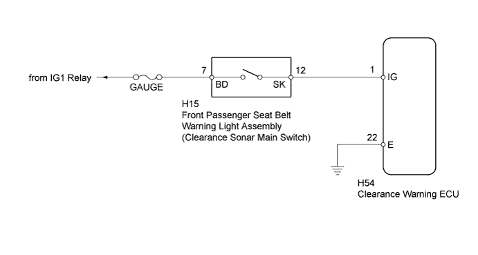
INSPECTION PROCEDURE
Note
Inspect the fuses for circuits related to this system before performing the following inspection procedure.
PROCEDURE
-
CHECK CLEARANCE WARNING ECU
-
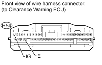
Disconnect the H54 clearance warning ECU connector.
-
Measure the voltage according to the value(s) in the table below.
Standard Voltage Tester Connection Switch Condition Specified Condition H54-1 (IG) - H54-22 (E) Ignition switch ON, clearance sonar main switch on 11 to 14 V
NG 
CHECK HARNESS AND CONNECTOR (CLEARANCE WARNING ECU - BODY GROUND) Click here
OK 
PROCEED TO NEXT SUSPECTED AREA SHOWN IN PROBLEM SYMPTOMS TABLE Click here
-
-
CHECK HARNESS AND CONNECTOR (CLEARANCE WARNING ECU - BODY GROUND)
-

Disconnect the H54 clearance warning ECU connector.
-
Measure the resistance according to the value(s) in the table below.
Standard Resistance Tester Connection Condition Specified Condition H54-22 (E) - Body ground Always Below 1 Ω
NG 
REPAIR OR REPLACE HARNESS OR CONNECTOR
OK 
-
-
CHECK HARNESS AND CONNECTOR (CLEARANCE SONAR MAIN SWITCH - BATTERY)
-
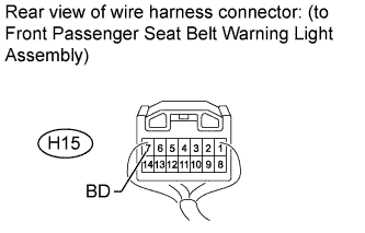
Disconnect the H15 front passenger seat belt warning light assembly connector.
-
Measure the voltage according to the value(s) in the table below.
Standard Voltage Tester Connection Switch Condition Specified Condition H15-7 (BD) - Body ground Ignition switch ON 11 to 14 V
NG
REPAIR OR REPLACE HARNESS OR CONNECTOR
OK
-
-
INSPECT FRONT PASSENGER SEAT BELT WARNING LIGHT ASSEMBLY (CLEARANCE WARNING MAIN SWITCH)
-
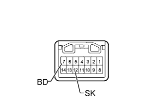
Remove the front passenger seat belt warning light assembly Click here.
-
Measure the resistance according to the value(s) in the table below.
Standard Resistance Tester Connection Switch Condition Specified Condition 7 (BD) - 12 (SK) Ignition switch ON, clearance sonar main switch off Below 1 Ω 7 (BD) - 12 (SK) Ignition switch ON, clearance sonar main switch on 10 kΩ or higher
NG
REPLACE FRONT PASSENGER SEAT BELT WARNING LIGHT ASSEMBLY Click here
OK
REPAIR OR REPLACE HARNESS OR CONNECTOR (CLEARANCE WARNING ECU - FRONT PASSENGER SEAT BELT WARNING LIGHT ASSEMBLY)
-