TOYOTA PARKING ASSIST-SENSOR SYSTEM Front Corner Clearance Sonar Sensor RH Circuit
DESCRIPTION
The ultrasonic sensor sends and receives ultrasonic waves. Based on the received wave, the sensor calculates the approximate distance between the vehicle and the obstacle, and sends the distance value as a signal to the clearance warning ECU.
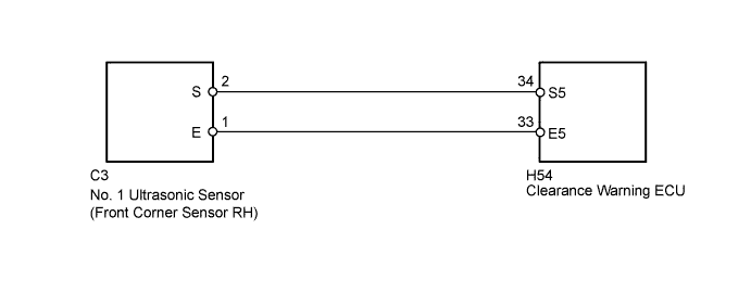
WIRING DIAGRAM
INSPECTION PROCEDURE
PROCEDURE
-
INSPECT NO. 1 ULTRASONIC SENSOR (FRONT CORNER SENSOR RH)
-
Remove the No. 1 ultrasonic sensor (front corner sensor RH) Click here.
-
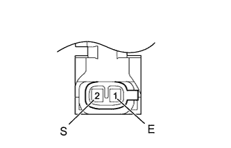
Measure the resistance according to the value(s) in the table below.
Standard Resistance Tester Connection Condition Specified Condition 1 (E) - 2 (S) Always 20 to 40 kΩ
NG 
REPLACE NO. 1 ULTRASONIC SENSOR (FRONT CORNER SENSOR RH) Click here
OK 
-
-
CHECK HARNESS AND CONNECTOR (FRONT CORNER SENSOR RH - CLEARANCE WARNING ECU)
-
Disconnect the C3 No. 1 ultrasonic sensor (front corner sensor RH) connector.
-
Disconnect the H54 clearance warning ECU connector.
-
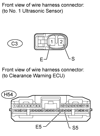
Measure the resistance according to the value(s) in the table below.
Standard Resistance Tester Connection Condition Specified Condition C3-2 (S) - H54-34 (S5) Always Below 1 Ω C3-1 (E) - H54-33 (E5) Always Below 1 Ω C3-2 (S) - Body ground Always 10 kΩ or higher C3-1 (E) - Body ground Always 10 kΩ or higher
NG
REPAIR OR REPLACE HARNESS OR CONNECTOR
OK 
PROCEED TO NEXT SUSPECTED AREA SHOWN IN PROBLEM SYMPTOMS TABLE Click here
-