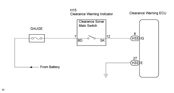
CLEARANCE SONAR SYSTEM Clearance Sonar Main Switch Circuit
DESCRIPTION
Turning this switch on activates the clearance sonar system.
WIRING DIAGRAM
INSPECTION PROCEDURE
PROCEDURE
-
INSPECT CLEARANCE WARNING ECU
-
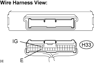
Disconnect the H33 connector from the clearance warning ECU.
-
Measure the voltage according to the value(s) in the table below.
Voltage Tester connection
(Symbols)
Condition Specified condition H33-8 (IG) - H33-27 (E)
-
Ignition switch ON
-
Clearance sonar main switch ON
10 to 14 V -
OK 
RETURN TO THE ORIGINAL INSPECTION FLOW BECAUSE THE CHECK RESULT IS NORMAL
NG 
-
-
CHECK HARNESS AND CONNECTOR (CLEARANCE WARNING ECU - BODY GROUND)
-
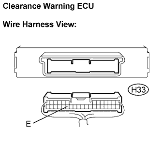
Measure the resistance according to the value(s) in the table below.
Resistance Tester connection
(Symbols)
Condition Specified condition H33-27 (E) -
Body ground
Always Below 1 Ω
NG
REPAIR OR REPLACE HARNESS OR CONNECTOR
OK
-
-
INSPECT CLEARANCE WARNING INDICATOR
-
Remove the clearance warning indicator.
-
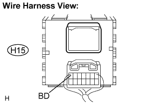
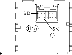
Disconnect the H15 connector from the clearance warning indicator.
-
Measure the voltage according to the value(s) in the table below.
Voltage Tester connection
(Symbols)
Condition Specified condition H15-7 (BD) -
Body ground
Ignition switch ON 10 to 14 V
NG
REPAIR OR REPLACE HARNESS OR CONNECTOR
OK
-
-
INSPECT CLEARANCE WARNING INDICATOR
-
Measure the resistance according to the value(s) in the table below.
Resistance Tester connection
(Symbols)
Condition Specified condition H15-7 (BD) -
H15-12 (SK)
Clearance sonar main switch OFF 10 kΩ or higher H15-7 (BD) -
H15-12 (SK)
Clearance sonar main switch ON Below 1 Ω
NG
REPLACE CLEARANCE WARNING INDICATOR
OK 
REPAIR OR REPLACE HARNESS OR CONNECTOR (CLEARANCE WARNING ECU - CLEARANCE WARNING INDICATOR)
-