CLEARANCE SONAR SYSTEM Back Sonar Sensor RH Circuit
DESCRIPTION
An ultrasonic sensor consists of a sensor portion that transmits and receives ultrasonic waves and a pre-amplifier that amplifies them. The ultrasonic sensor outputs the ultrasonic transmission and reception signals to the clearance warning ECU.
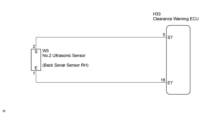
WIRING DIAGRAM
INSPECTION PROCEDURE
PROCEDURE
-
INSPECT NO.2 ULTRASONIC SENSOR
-
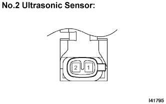
Remove No.2 ultrasonic sensor.
-
Measure the resistance according to the value(s) in the table below.
Resistance Tester connection Condition Specified condition 1 - 2 Always 900 +- 300 kΩ
NG 
REPLACE NO.2 ULTRASONIC SENSOR
OK 
-
-
CHECK HARNESS AND CONNECTOR (CLEARANCE WARNING ECU - NO.2 ULTRASONIC SENSOR)
-
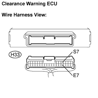
Disconnect the H33 connector from the clearance warning ECU.
-
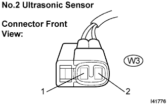
Disconnect the W3 connector from the No.2 ultrasonic sensor.
-
Measure the resistance according to the value(s) in the table below.
Resistance Tester connection
(Symbols)
Condition Specified condition H33-5 (S7) - W3-2 (S) Always Below 1 Ω H33-18 (E7) - W3-1 (E) Always Below 1 Ω H33-5 (S7) -
Body ground
Always 10 kΩ or higher H33-18 (E7) -
Body ground
Always 10 kΩ or higher
NG
REPAIR OR REPLACE HARNESS OR CONNECTOR
OK 
RETURN TO THE ORIGINAL INSPECTION FLOW BECAUSE THE CHECK RESULT IS NORMAL
-