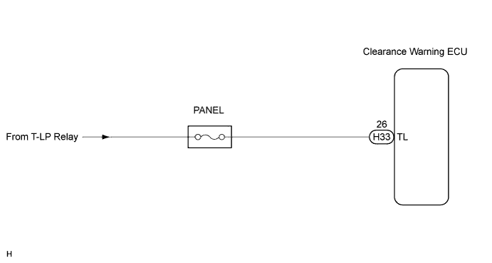
CLEARANCE SONAR SYSTEM Dimmer Signal Circuit
DESCRIPTION
The taillight relay turns on when the light control switch is turned to the "TAIL" or "HEAD" position. The clearance warning ECU dims the clearance sonar display when it receives a tail relay ON signal.
WIRING DIAGRAM
INSPECTION PROCEDURE
PROCEDURE
-
INSPECT CLEARANCE WARNING ECU
-
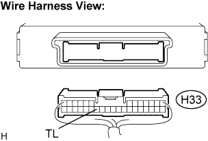
Disconnect the clearance warning ECU H33 connector.
-
Measure the voltage according to the value(s) in the table below.
Voltage Tester connection
(Symbols)
Condition Specified condition H33-26 (TL) -
Body ground
Light control switch "TAIL" or "HEAD" position 10 to 14 V
NG 
REPAIR OR REPLACE HARNESS OR CONNECTOR
OK 
RETURN TO THE ORIGINAL INSPECTION FLOW BECAUSE THE CHECK RESULT IS NORMAL
-