CLEARANCE SONAR SYSTEM Reverse Signal Circuit
DESCRIPTION
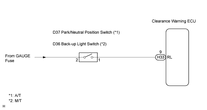
The clearance warning ECU receives the reverse signal from the back-up light switch (M/T) or park/neutral position switch (A/T).
WIRING DIAGRAM
INSPECTION PROCEDURE
PROCEDURE
-
INSPECT CLEARANCE WARNING ECU
-
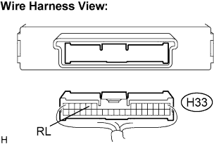
Disconnect the H33 connector from the clearance warning ECU.
-
Measure the voltage according to the value(s) in the table below.
Voltage Tester connection
(Symbols)
Condition Specified condition H33-9 (RL) -
Body ground
Ignition switch ON, shift lever R position 10 to 14 V
OK 
RETURN TO THE ORIGINAL INSPECTION FLOW BECAUSE THE CHECK RESULT IS NORMAL
NG 
-
-
CHECK HARNESS AND CONNECTOR
-
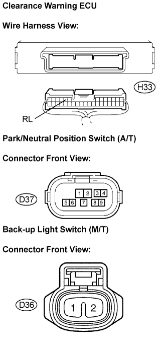
Disconnect the connector from the back-up light switch (M/T) or park/neutral position switch (A/T).
-
Measure the resistance according to the value(s) in the table below.
Resistance Tester connection
(Symbols)
Condition Specified condition H33-9 (RL) - D37-1 (*1) Always Below 1 Ω H33-9 (RL) - D36-1 (*2) Always Below 1 Ω H33-9 (RL) -
Body ground
Always 10 kΩ or higher *1: A/T
*2: M/T
NG
REPAIR OR REPLACE HARNESS OR CONNECTOR
OK
-
-
CHECK TYPE
-
Choose type to be inspected.
Result Type Go to step A/T A M/T B
B 
INSPECT BACK UP LIGHT SWITCH Click here
A
-
-
INSPECT PARK/NEUTRAL POSITION SWITCH
-
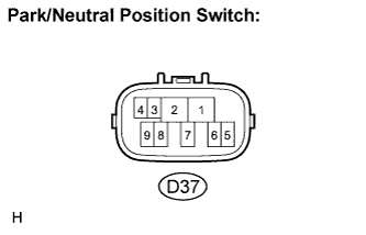
Disconnect the park/neutral position switch connector D37.
-
Measure the resistance according to the value(s) in the table below.
Resistance Tester connection Condition Specified condition D37-1 - D37-2 Shift lever is moved to R position. Below 1 Ω D37-1 - D37-2 Shift lever is moved to any position except R. 10 kΩ or higher
NG
REPLACE PARK/NEUTRAL POSITION SWITCH
OK 
REPAIR OR REPLACE HARNESS OR CONNECTOR
-
-
INSPECT BACK UP LIGHT SWITCH
-
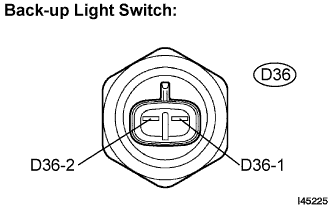
Disconnect the back-up light switch connector D36.
-
Measure the resistance according to the value(s) in the table below.
Resistance Tester connection Condition Specified condition D36-1 - D36-2 Shift lever is moved to R position. Below 1 Ω D36-1 - D36-2 Shift lever is moved to any position except R. 10 kΩ or higher
NG
REPLACE BACK UP LIGHT SWITCH
OK
REPAIR OR REPLACE HARNESS OR CONNECTOR
-