CLEARANCE SONAR SYSTEM TERMINALS OF ECU

-
CLEARANCE WARNING ECU

Terminal No. (Symbols) Wiring color Terminal description Condition Specified condition H33-1 (S1) - H33-14 (E1) R - G Front clearance sonar sensor RH When signals are transmitted from the ECU to the front clearance sonar sensor RH Pulse generation
Refer to waveform 3
H33-2 (S4) - H33-15 (E4) B - W Front clearance sonar sensor LH When signals are transmitted from the ECU to the front clearance sonar sensor LH Pulse generation
Refer to waveform 3
H33-3 (S5) - H33-16 (E5) B - Y Rear clearance sonar sensor RH When signals are transmitted from the ECU to the rear clearance sonar sensor RH Pulse generation
Refer to waveform 3
H33-4 (S6) - H33-17 (E6) W - R Rear clearance sonar sensor LH When signals are transmitted from the ECU to the rear clearance sonar sensor LH Pulse generation
Refer to waveform 3
H33-5 (S7) - H33-18 (E7) P - V Back sonar sensor RH When signals are transmitted from the ECU to the back sonar sensor RH Pulse generation
Refer to waveform 2
H33-6 (S8) - H33-19 (E8) L - Y Back sonar sensor LH When signals are transmitted from the ECU to the back sonar sensor LH Pulse generation
Refer to waveform 2
H33-8 (IG) - H33-27 (E) L-R - W-B Power source Ignition switch ON, clearance sonar main switch OFF → ON Below 1 V →
10 to 14 V
H33-9 (RL) - H33-27 (E) L - W-B Reverse signal Ignition switch ON, shift position is except R position → R Below 1 V →
10 to 14 V
H33-10 (CBZ) - H33-27 (E) L-W - W-B Clearance warning buzzer Clearance sonar sounding (when the clearance sonar senses something) Pulse generation
Refer to waveform 1
H33-11 (L7) - H33-27 (E) Y - W-B Back sonar indicator Back sonar indicator OFF → ON 10 to 14 V → Below 3 V H33-12 (L6) - H33-27 (E) Y-B - W-B Clearance sonar indicator rear LH Clearance sonar indicator rear LH OFF → ON 10 to 14 V → Below 3 V H33-13 (L5) - H33-27 (E) Y-R - W-B Clearance sonar indicator rear RH Clearance sonar indicator rear RH OFF → ON 10 to 14 V → Below 3 V H33-14 (E1) - H33-27 (E) G - W-B Ground (for front clearance sonar sensor RH) Always Below 1 V H33-15 (E4) - H33-27 (E) W - W-B Ground (for front clearance sonar sensor LH) Always Below 1 V H33-16 (E5) - H33-27 (E) Y - W-B Ground (for rear clearance sonar sensor RH) Always Below 1 V H33-17 (E6) - H33-27 (E) R - W-B Ground (for rear clearance sonar sensor LH) Always Below 1 V H33-18 (E7) - H33-27 (E) V - W-B Ground (for back sonar sensor RH) Always Below 1 V H33-19 (E8) - H33-27 (E) Y - W-B Ground (for back sonar sensor LH) Always Below 1 V H33-25 (SPD) - H33-27 (E) P-L - W-B Speed signal When driving at low speed Pulse generation H33-26 (TL) - H33-27 (E) G - W-B Dimmer signal Light control switch off
→ TAIL or HEAD
Below 1 V →
10 to 14 V
H33-27 (E) - Body ground W-B -
Body ground
Ground Always Below 1 V H33-28 (PL) - H33-27 (E) R-W - W-B Parking position signal Shift lever is P position (A/T) 10 to 14 V H33-30 (L10) - H33-27 (E) L - W-B Power indicator Ignition switch ON, clearance sonar main switch OFF → ON 10 to 14 V →
Below 3 V
H33-31 (L4) - H33-27 (E) Y-G - W-B Front clearance sonar indicator LH Front clearance sonar indicator LH OFF → ON 10 to 14 V → Below 3 V H33-32 (L1) - H33-27 (E) L-B - W-B Front clearance sonar indicator RH Front clearance sonar indicator RH OFF → ON 10 to 14 V → Below 3 V -
CLEARANCE WARNING INDICATOR

Terminal No. (Symbols) Wiring color Terminal description Condition Specified condition H15-1 (E) - Body ground W-B -
Body ground
Ground Always Below 1 V H15-2 (RR) - H15-1 (E) Y-R - W-B Rear clearance sonar indicator RH Rear clearance sonar indicator RH OFF → ON 10 to 14 V → Below 3 V H15-3 (FR) - H15-1 (E) L-B - W-B Front clearance sonar indicator RH Front clearance sonar indicator RH OFF → ON 10 to 14 V → Below 3 V H15-4 (RL) - H15-1 (E) Y-B - W-B Rear clearance sonar indicator LH Rear clearance sonar indicator LH OFF → ON 10 to 14 V → Below 3 V H15-5 (FL) - H15-1 (E) Y-G - W-B Front clearance sonar indicator LH Front clearance sonar indicator LH OFF → ON 10 to 14 V → Below 3 V H15-7 (BD) - H15-1 (E) L-R - W-B Power source Always 10 to 14 V H15-9 (BK) - H15-1 (E) Y - W-B Back sonar indicator Back sonar indicator OFF → ON 10 to 14 V → Below 3 V H15-10 (OP) - H15-1 (E) L - W-B Power indicator Ignition switch ON, clearance sonar main switch OFF → ON 10 to 14 V → Below 3 V H15-11 (BZ) - H15-1 (E) L-W - W-B Clearance warning buzzer Clearance sonar sounding (when the clearance sonar senses something) Pulse generation
Refer to waveform 1
H15-12 (SK) - H15-1 (E) L-R - W-B Power source Ignition switch ON, clearance sonar main switch OFF → ON Below 1 V →
10 to 14 V
-
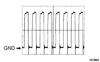
Reference: waveform 1
Tech Tips
-
Terminal: CBZ - E, BZ - E
-
Gauge set: 2 V/DIV, 500 μs/DIV
-
Condition: When the clearance sonar is detecting.
-
-
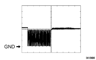
Reference: waveform 2
Tech Tips
-
Terminal: S7 - E7, S8 - E8
-
Gauge set: 2 V/DIV, 100 μs/DIV
-
Condition: When the clearance sonar is not detecting.
-
-
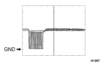
Reference: waveform 3
Tech Tips
-
Terminal: S1 - E1, S4 - E4, S5 - E5, S6 - E6
-
Gauge set: 2 V/DIV, 100 μs/DIV
-
Condition: When the back sonar is not detecting.
-
-