CLEARANCE SONAR SYSTEM OPERATION CHECK

-
DETECTION RANGE MEASUREMENT AND INDICATOR CHECK
-
Turn the ignition switch to the ON position.
-
Move the shift lever to the R position.
Note
Apply the parking brake securely so that the vehicle does not move.
-
Turn the clearance sonar main switch on.
-
Move a φ 60 mm (2.36 in.) pole around the sensors to measure the detection ranges of the sensors.
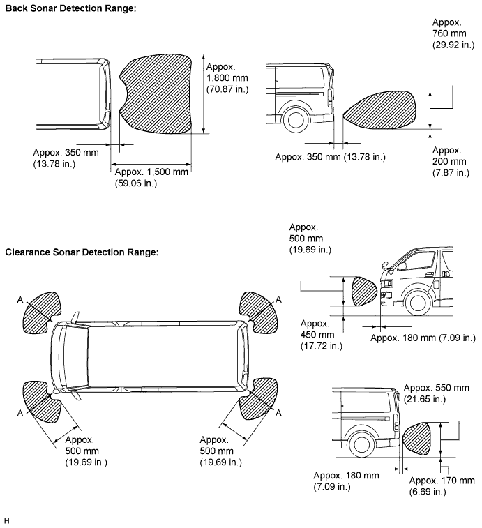
Note
The measured detection ranges are for a φ 60 mm (2.36 in.) pole. The detection ranges for walls and other obstacles are different.
-
Check the indicator and the buzzer sounding condition when the back sonar sensors detect an obstacle.
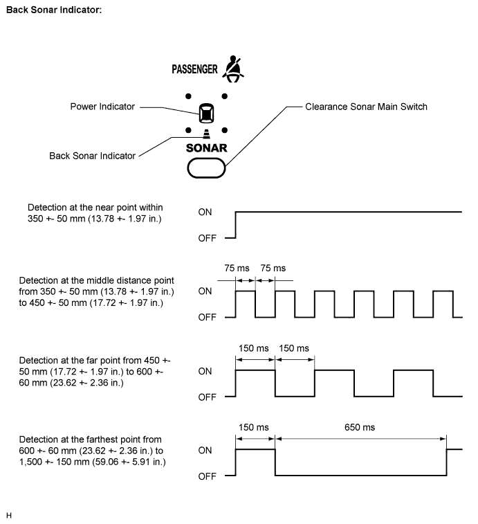
Tech Tips
Since sound waves are used for the detection range measurement, the detection ranges may vary a little due to the outside air temperature.
-
Check the indicator and the buzzer sounding condition when the rear clearance sonar sensors detect an obstacle.
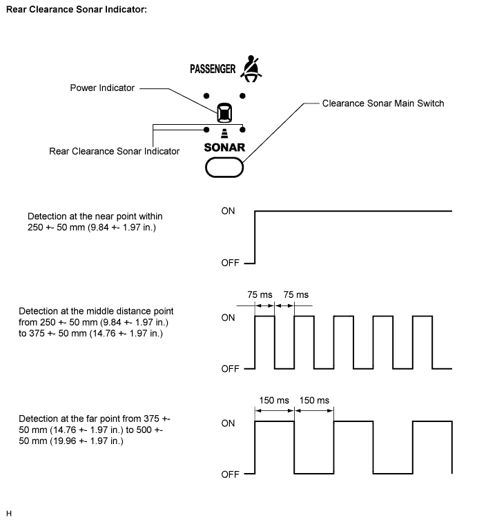
Tech Tips
Since sound waves are used for the detection range measurement, the detection ranges may vary a little due to the outside air temperature.
-
Check the indicator and the buzzer sounding condition when the front clearance sonar sensors detect an obstacle.
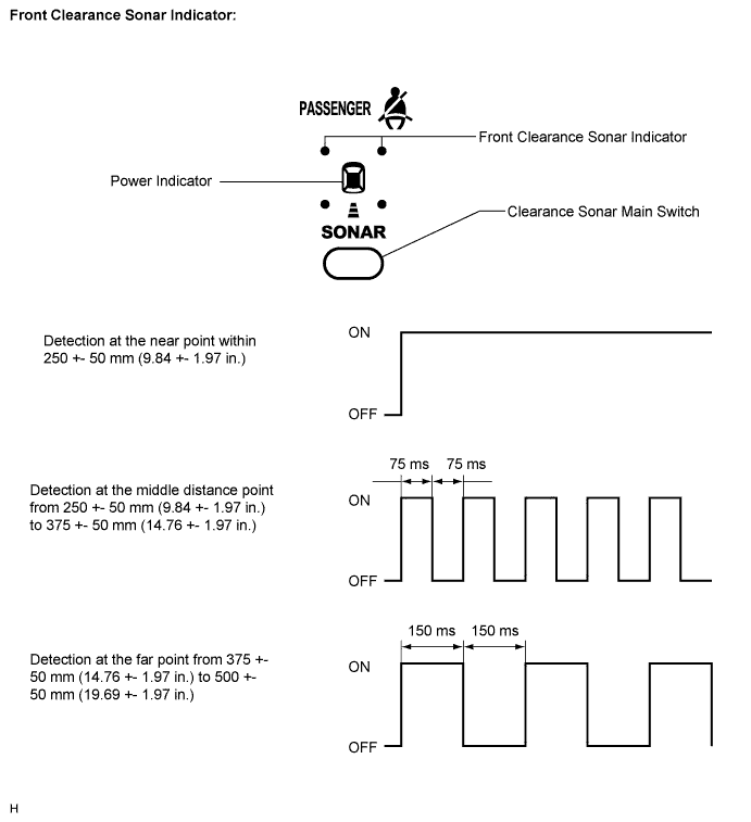
Tech Tips
Since sound waves are used for the detection range measurement, the detection ranges may vary a little due to the outside air temperature.
-
-
CHECK INITIAL CHECK FUNCTION
-
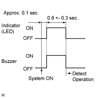
Turn the ignition switch to the ON position.
-
Move the shift lever to the R position.
-
Turn the back and clearance sonar main switch on and check the indicators (LEDs) and buzzer conditions.
Tech Tips
-
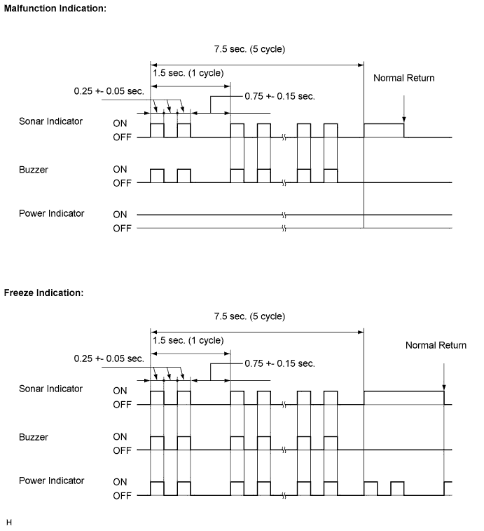
If the system detects an open circuit in any sensor circuit, or any sensor does not work (unable to detect because the sensor is wet or frozen), the LEDs and buzzer operate as shown in the illustration below.
-
If the clearance sonar sensor circuits return to normal, the clearance sonar sensors will automatically return to normal operation.
-
If the back sonar sensor circuits return to normal, the back sonar sensors will return to normal operation after the ignition switch is first turned off and then on again.
-
-