CLEARANCE SONAR SYSTEM Clearance Warning Buzzer Circuit
DESCRIPTION
The clearance warning ECU receives the ultrasonic sensor signal to sound the clearance warning buzzer.
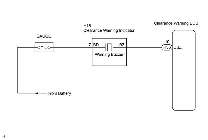
WIRING DIAGRAM
INSPECTION PROCEDURE
PROCEDURE
-
CHECK HARNESS AND CONNECTOR (CLEARANCE WARNING ECU - CLEARANCE WARNING INDICATOR)
-
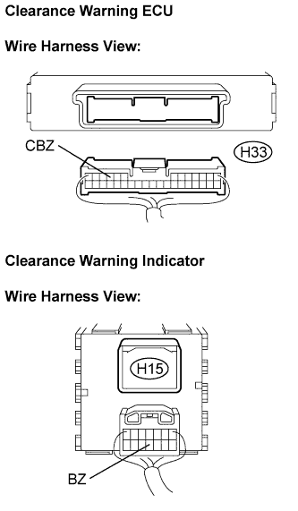
Disconnect the connectors from the clearance warning ECU H33 and clearance warning indicator H15.
-
Measure the resistance according to the value(s) in the table below.
Resistance Tester connection
(Symbols)
Condition Specified condition H33-10 (CBZ) -
H15-11 (BZ)
Always Below 1 Ω H33-10 (CBZ) -
Body ground
Always 10 kΩ or higher
NG 
REPAIR OR REPLACE HARNESS OR CONNECTOR
OK 
RETURN TO THE ORIGINAL INSPECTION FLOW BECAUSE THE CHECK RESULT IS NORMAL
-