TOYOTA PARKING ASSIST-SENSOR SYSTEM Vehicle Speed Signal Circuit
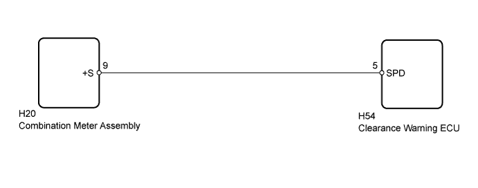
WIRING DIAGRAM
INSPECTION PROCEDURE
PROCEDURE
-
CHECK COMBINATION METER ASSEMBLY (SPD SIGNAL)
-
Disconnect the H54 clearance warning ECU connector.
-
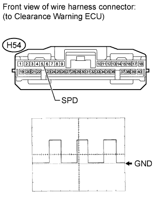
Using an oscilloscope, check the signal waveform of the meter.
Measurement Condition Item Content Tester Connection H54-5 (SPD) - Body ground Tool Setting 5 V/DIV., 20 msec./DIV. Vehicle Condition Drive vehicle at 20 km/h (12 mph) OK Waveform is as shown in illustration. Tech Tips
As the vehicle speed increases, the wavelength shortens.
NG 
CHECK HARNESS AND CONNECTOR (CLEARANCE WARNING ECU - COMBINATION METER) Click here
OK 
PROCEED TO NEXT SUSPECTED AREA SHOWN IN PROBLEM SYMPTOMS TABLE Click here
-
-
CHECK HARNESS AND CONNECTOR (CLEARANCE WARNING ECU - COMBINATION METER)
-
Disconnect the H54 clearance warning ECU connector.
-
Disconnect the H20 combination meter assembly connector.
-
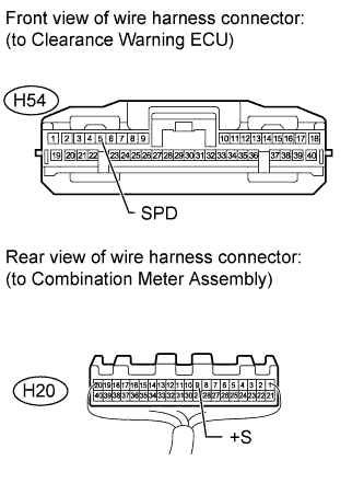
Measure the resistance according to the value(s) in the table below.
Standard Resistance Tester Connection Condition Specified Condition H54-5 (SPD) - H20-9 (+S) Always Below 1 Ω H54-5 (SPD) - Body ground Always 10 kΩ or higher
NG 
REPAIR OR REPLACE HARNESS OR CONNECTOR
OK
GO TO METER / GAUGE SYSTEM Click here
-