STEERING PAD SWITCH INSPECTION

-
INSPECT STEERING PAD SWITCH LH
-
Inspect the steering pad switch LH.
-
Measure the resistance according to the value(s) in the table below.
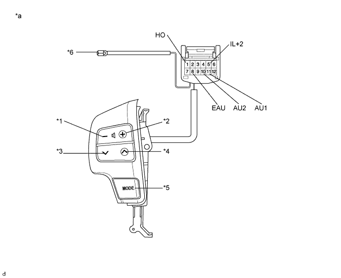
Text in Illustration *1 VOL- *2 VOL+ *3 SEEK- *4 SEEK+ *5 MODE *6 Horn Wire *a Component without harness connected
(Steering Pad Switch LH)
- - Standard Resistance Tester Connection Switch Condition Specified Condition 11 (AU1) - 8 (EAU) No switch pushed 95 to 105 kΩ VOL+ switch pushed 950 to 1050 Ω VOL- switch pushed 2955 to 3265 Ω SEEK+ switch pushed Below 2.5 Ω SEEK- switch pushed 313 to 345 Ω MODE switch pushed 95 to 105 kΩ A10 (AU2) - A8 (EAU) No switch pushed 95 to 105 kΩ VOL+ switch pushed VOL- switch pushed SEEK+ switch pushed SEEK- switch pushed MODE switch pushed Below 2.5 Ω 1(HO) - Horn Wire Always Below 2.5 Ω If the result is not as specified, replace the steering pad switch LH.
-
-
Check the illumination.
-
Connect the battery positive (+) lead to terminal 5(IL+2) and the negative (-) lead to terminal 8(EAU) of the steering pad switch LH connector.
-
Check that the steering pad switch LH illumination comes on.
OK Steering pad switch illumination comes on. If the result is not as specified, replace the steering pad switch LH.
-
-