AUDIO AND VISUAL SYSTEM Radio Receiver Power Source Circuit
DESCRIPTION
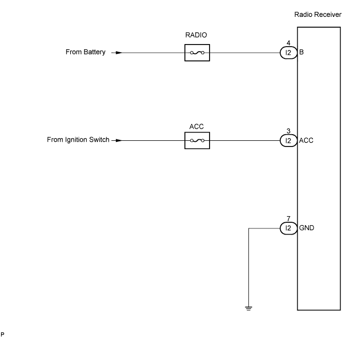
This circuit provides power to the radio receiver.
WIRING DIAGRAM
INSPECTION PROCEDURE
PROCEDURE
-
INSPECT RADIO RECEIVER
-
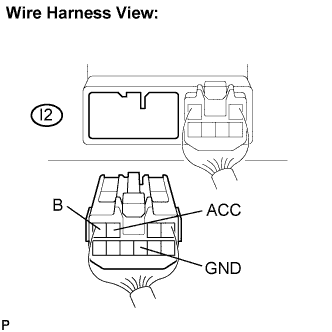
Disconnect the radio receiver I2 connector.
-
Measure the resistance according to the value in the table below.
Standard resistance Tester connection Condition Specified condition GND - Body ground Always Below 1 Ω -
Measure the voltage according to the values in the table below.
Standard voltage Tester connection Condition Specified condition B - GND Always 10 to 14V ACC - GND Ignition SW ACC 10 to 14V
OK 
RETURN TO THE ORIGINAL INSPECTION FLOW BECAUSE THE CHECK RESULT IS NORMAL
NG 
REPAIR OR REPLACE HARNESS OR CONNECTOR
-