AUDIO AND VISUAL SYSTEM Speaker Circuit
DESCRIPTION
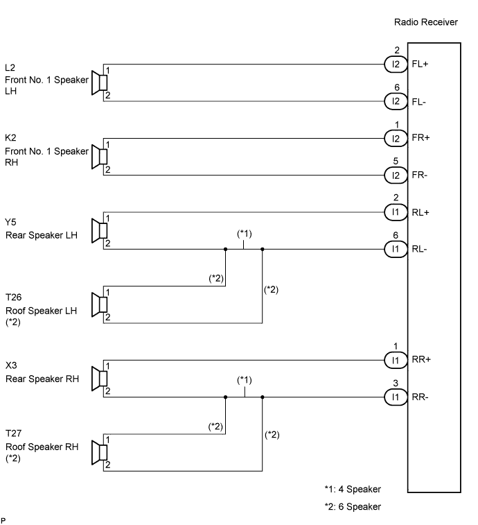
The sound signal that has been amplified by the radio receiver (built-in amplifier) is sent to the speakers from the radio receiver through this circuit.
WIRING DIAGRAM
INSPECTION PROCEDURE
PROCEDURE
-
CHECK HARNESS AND CONNECTOR
-
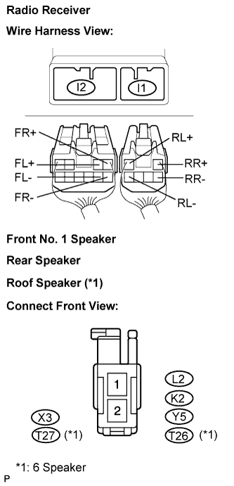
Disconnect the connectors shown in the illustration from the radio receiver and speakers.
-
Measure the resistance between the speaker and the radio receiver to check for an open circuit in the wire harness.
Standard resistance Below 1 Ω -
Measure the resistance between the speaker and body ground to check for a short circuit in the wire harness.
Standard resistance 10 kΩ or higher
NG 
REPAIR OR REPLACE HARNESS OR CONNECTOR
OK 
-
-
INSPECT FRONT NO. 1 SPEAKER
-
Resistance check.
-
Measure the resistance between the terminals of the speaker.
Standard resistance Approximately 4 Ω
-
NG
REPLACE FRONT NO. 1 SPEAKER
OK
-
-
INSPECT REAR SPEAKER
-
Resistance check.
-
Measure the resistance between the terminals of the speaker.
Standard resistance Approximately 6 Ω
-
NG
REPLACE REAR SPEAKER
OK
-
-
CONFIRM MODEL
Result Result Proceed to 6 Speaker A 4 Speaker B
B
RETURN TO THE ORIGINAL INSPECTION FLOW BECAUSE THE CHECK RESULT IS NORMAL
A
-
INSPECT ROOF SPEAKER
-
Resistance check.
-
Measure the resistance between the terminals of the speaker.
Standard resistance Approximately 6 Ω
-
NG
REPLACE ROOF SPEAKER
OK 
RETURN TO THE ORIGINAL INSPECTION FLOW BECAUSE THE CHECK RESULT IS NORMAL
-