AUDIO AND VISUAL SYSTEM Illumination Circuit
DESCRIPTION
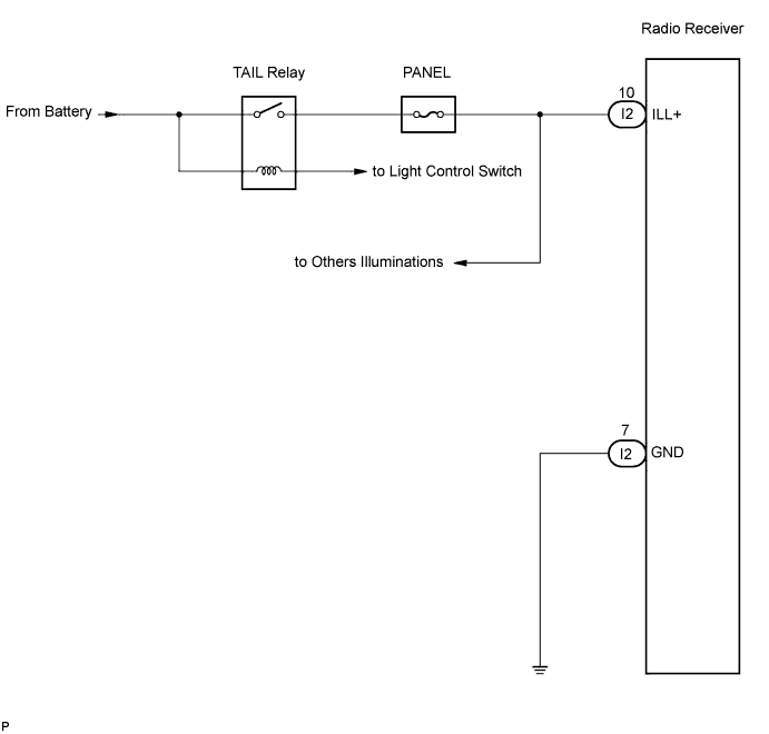
Power is supplied to the radio receiver illumination when the light control switch is in the TAIL or HEAD position.
WIRING DIAGRAM
INSPECTION PROCEDURE
PROCEDURE
-
CHECK ILLUMINATION
-
Check if the illumination for the radio receiver, A/T shift lever illumination, room light switch, A/C switch or others (blower switch, rear window defogger switch, etc.) comes on when the light control switch is turned to the HEAD or TAIL position.
Result Result Proceed to Illumination comes on for all components except radio receiver. A No illumination comes on. B
B 
GO TO LIGHTING SYSTEM
A 
-
-
INSPECT RADIO RECEIVER
-
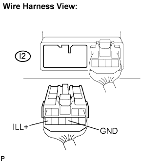
Disconnect the radio receiver I2 connector.
-
Measure the resistance according to the value(s) in the table below.
Standard resistance Tester connection Condition Specified condition GND - Body gorund Always Below 1 Ω -
Measure the voltage according to the value(s) in the table below.
Standard voltage Tester connection Condition Specified condition ILL+ - Body ground Light control SW HEAD or TAIL 10 to 14 V
NG
REPAIR OR REPLACE HARNESS OR CONNECTOR
OK 
RETURN TO THE ORIGINAL INSPECTION FLOW BECAUSE THE CHECK RESULT IS NORMAL
-