METER / GAUGE SYSTEM Fuel Receiver Gauge Malfunction
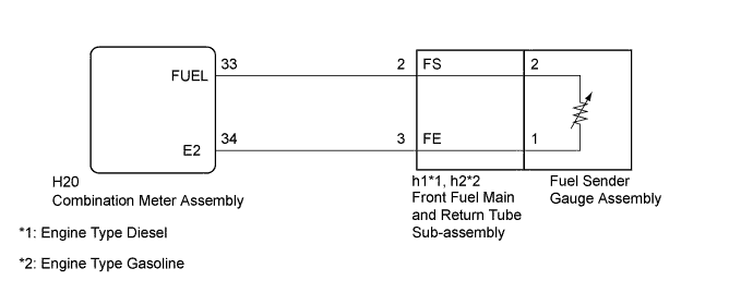
WIRING DIAGRAM
INSPECTION PROCEDURE
Note
Be careful of flames.
PROCEDURE
-
PERFORM ACTIVE TEST USING GTS (FUEL METER OPERATION)
-
Use the Active Test to check the operation of the fuel receiver gauge Click here.
Combination Meter Tester Display Test Part Control Range Diagnostic Note Fuel Meter Operation Fuel receiver gauge OFF, Sender E, Empty, Warning, 1/4, 1/2, 3/4, Full or Sender F - OK Fuel receiver gauge is normal.
NG 
REPLACE COMBINATION METER ASSEMBLY Click here
OK 
-
-
READ VALUE USING GTS (FUEL INPUT)
-
Use the Data List to check if the fuel receiver gauge is operating properly Click here.
Combination Meter Tester Display Measurement Item/Range Normal Condition Diagnostic Note Fuel Input Fuel input signal/Min.: 0, Max. 127.5 Current fuel level displayed Unit: Liters. OK Fuel amount value displayed on the GTS is almost the same as needle indication.
NG
REPLACE COMBINATION METER ASSEMBLY Click here
OK
-
-
CHECK HARNESS AND CONNECTOR (COMBINATION METER ASSEMBLY - FRONT FUEL MAIN AND RETURN TUBE SUB-ASSEMBLY)
-
Disconnect the H20 combination meter assembly connector.
-
Disconnect the h1*1 or h2*2 front fuel main and return tube sub-assembly connector.
-
*1: Engine Type Diesel
-
*2: Engine Type Gasoline
-
-
Measure the resistance according to the value(s) in the table below.
Standard Resistance Engine Type Diesel Tester Connection Condition Specified Condition H20-33 (FUEL) - h1-2 Always Below 1 Ω H20-34 (E2) - h1-3 H20-33 (FUEL) or h1-2 - Body ground Always 10 kΩ or higher H20-34 (E2) or h1-3 - Body ground Engine Type Gasoline Tester Connection Condition Specified Condition H20-33 (FUEL) - h1-2 Always Below 1 Ω H20-34 (E2) - h1-3 H20-33 (FUEL) or h1-2 - Body ground Always 10 kΩ or higher H20-34 (E2) or h1-3 - Body ground
NG
REPAIR OR REPLACE HARNESS OR CONNECTOR
OK
-
-
INSPECT FRONT FUEL MAIN AND RETURN TUBE SUB-ASSEMBLY
-
Remove the front fuel main and return tube sub-assembly.
-
for 1KD-FTV: Click here
-
for 2KD-FTV: Click here
-
for 5L-E: Click here
-
for 1TR-FE: Click here
-
for 2TR-FE: Click here
-
-
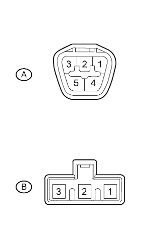
Measure the resistance according to the value(s) in the table below.
Standard Resistance Tester Connection Condition Specified Condition A-2 - B-2 Always Below 1 Ω A-3 - B-1
-
*: Replacement procedure;
-
for 1KD-FTV: Click here
-
for 2KD-FTV: Click here
-
for 5L-E: Click here
-
for 1TR-FE: Click here
-
for 2TR-FE: Click here
-
NG
REPLACE FRONT FUEL MAIN AND RETURN TUBE SUB-ASSEMBLY*
OK
-
-
INSPECT FUEL SENDER GAGE ASSEMBLY
-
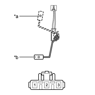
Text in Illustration *a F (Upper) *b E (Lower) Remove the fuel sender gauge assembly.
-
for 1KD-FTV: Click here
-
for 2KD-FTV: Click here
-
for 5L-E: Click here
-
for 1TR-FE: Click here
-
for 2TR-FE: Click here
-
-
Measure the resistance according to the value(s) in the table below.
Standard Resistance Tester Connection Condition Specified Condition 1 - 2 Float level is F (upper) 13.5 to 16.5 Ω Float level is E (lower) 405.5 to 414.5 Ω Tech Tips
*: Replacement procedure;
-
for 1KD-FTV: Click here
-
for 2KD-FTV: Click here
-
for 5L-E: Click here
-
for 1TR-FE: Click here
-
for 2TR-FE: Click here
-
NG
REPLACE FUEL SENDER GAUGE ASSEMBLY*
OK 
REPLACE COMBINATION METER ASSEMBLY Click here
-