METER / GAUGE SYSTEM Fuel Receiver Gauge Malfunction
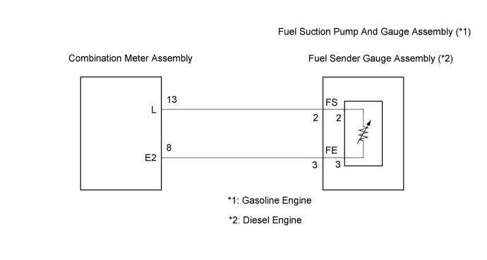
WIRING DIAGRAM
INSPECTION PROCEDURE
PROCEDURE
-
SYSTEM CHECK
Result Condition Go To Step Fuel level warning light operates normally. B Any malfunction except above. A
B 
REPLACE COMBINATION METER ASSEMBLY
A 
-
INSPECT COMBINATION METER ASSEMBLY
-
Disconnect the connector from the fuel sender gauge.
-
Measure the voltage according to the value(s) in the table below.
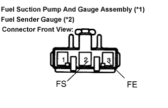
Standard Voltage Tester Connection Condition Specified Condition FS (2) - FE (3) Always 10 to 14 V *1: Gasoline engine
*2: Diesel engine
NG 
CHECK HARNESS AND CONNECTOR (BETWEEN COMBINATION METER AND FUEL SENDER GAUGE ASSEMBLY) Click here
OK
-
-
INSPECT FUEL SENDER GAUGE ASSEMBLY
-
Measure the resistance according to the value(s) in the table below.
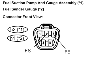
Standard Resistance Tester Connection Condition Specified Condition h2-2 (FS) - h2-3 (FE) (*1) Always 3.0 to 112.5 Ω h1-2 (FS) - h1-3 (FE) (*2) Always 3.0 to 112.5 Ω *1: Gasoline engine
*2: Diesel engine
NG
INSPECT FUEL SENDER GAUGE ASSEMBLY Click here
OK
-
-
INSPECT FUEL SENDER GAUGE ASSEMBLY
-
Short terminals 2 and 3 at the wire harness side.
-
Turn the ignition switch ON.
OK Fuel sender gauge needle indicates F or more. *1: Gasoline engine
*2: Diesel engine
OK
INSPECT FUEL SENDER GAUGE ASSEMBLY Click here
NG
-
-
CHECK HARNESS AND CONNECTOR (BETWEEN COMBINATION METER AND FUEL SENDER GAUGE ASSEMBLY)
-
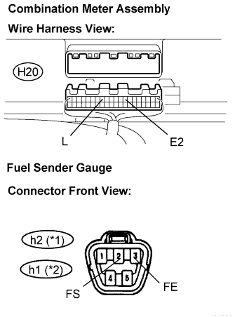
Disconnect the H20 and h2 (*1)/h1 (*2) connectors.
-
Measure the resistance according to the value(s) in the table below.
Standard Resistance Tester Connection Condition Specified Condition H20-13 (L) - h2-2 (FS) (*1) Always Below 1 Ω H20-8 (E2) - h2-3 (FE) (*1) Always Below 1 Ω H20-13 (L) - h1-2 (FS) (*2) Always Below 1 Ω H20-8 (E2) - h1-3 (FE) (*2) Always Below 1 Ω h2-2 (FS) - Body ground (*1) Always 10 kΩ or higher h1-2 (FS) - Body ground (*2) Always 10 kΩ or higher *1: Gasoline engine
*2: Diesel engine
NG
REPAIR OR REPLACE HARNESS OR CONNECTOR
OK 
REPLACE COMBINATION METER ASSEMBLY
-
-
INSPECT FUEL SENDER GAUGE ASSEMBLY
-
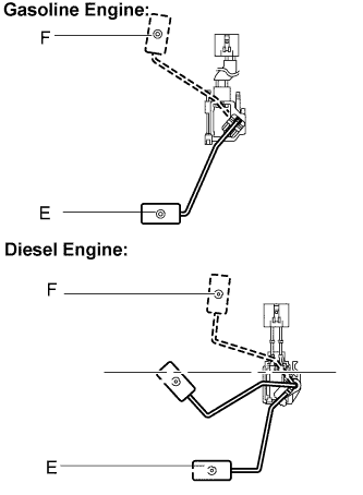
Check that the float moves between F (top) and E (bottom) smoothly.
OK The float moves between F (top) and E (bottom) smoothly. -
Measure the resistance according to the value(s) in the table below.
Standard Resistance (Gasoline Engine) Float Level Specified Resistance F 3.0 to 5.0 Ω E 107.5 to 112.5 Ω Standard Resistance (Diesel Engine) Float Level Specified Resistance F 3.0 to 5.0 Ω E 107.5 to 112.5 Ω
NG
REPLACE FUEL SENDER GAUGE ASSEMBLY
OK
END
-