METER / GAUGE SYSTEM Tachometer Malfunction
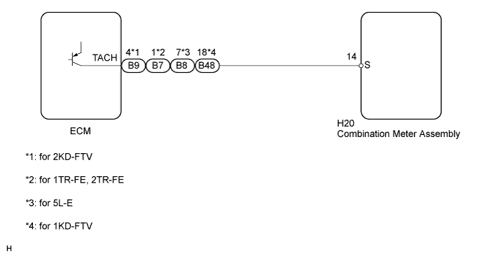
WIRING DIAGRAM
INSPECTION PROCEDURE
PROCEDURE
-
INSPECT COMBINATION METER ASSEMBLY
-
Check the input signal wave form using an oscilloscope.
-
Remove the combination meter assembly with the connector still connected.
-
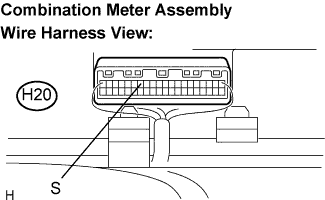
Connect the oscilloscope to terminal S (H20-14) and body ground.
-
Start the engine.
-
Check the signal wave form according to the condition(s) in the table below.
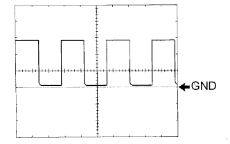
Item Condition Tester connection H20-14 (S) - Body ground Tool setting 5 V/DIV., 10 ms/DIV. Vehicle condition Ignition switch ON, engine idle speed OK The correct waveform appears as shown in the illustration.
-
NG 
CHECK HARNESS AND CONNECTOR (BETWEEN ECM AND COMBINATION METER) Click here
OK 
REPLACE COMBINATION METER ASSEMBLY
-
-
CHECK HARNESS AND CONNECTOR (BETWEEN ECM AND COMBINATION METER)
-
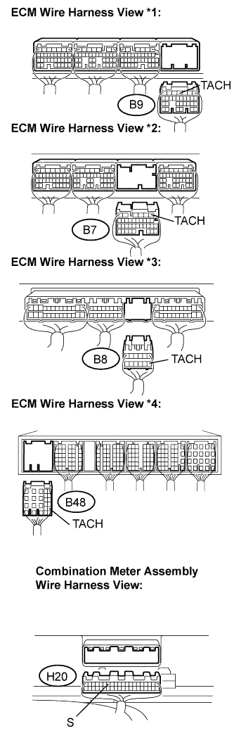
Disconnect the H20 and B9*1/B7*2/B8*3/B48*4 connectors.
-
Measure the resistance according to the value(s) in the table below.
Standard Resistance Tester Connection Condition Specified Condition B9-4 (TACH)*1 - H20-14 (S) Always Below 1 Ω B7-1 (TACH)*2 - H20-14 (S) Always Below 1 Ω B8-7 (TACH)*3 - H20-14 (S) Always Below 1 Ω B48-18 (TACH)*4 - H20-14 (S) Always Below 1 Ω H20-14 (S) - Body ground Always 10 kΩ or higher *1: for 2KD-FTV
*2: for 1TR-FE, 2TR-FE
*3: for 5L-E
*4: for 1KD-FTV
NG 
REPAIR OR REPLACE HARNESS OR CONNECTOR
OK
REPLACE ECM
-