METER / GAUGE SYSTEM Speedometer Malfunction
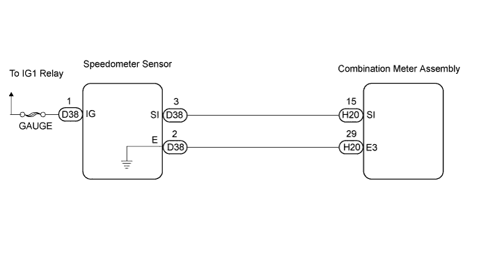
WIRING DIAGRAM
INSPECTION PROCEDURE
PROCEDURE
-
INSPECT COMBINATION METER ASSEMBLY
-
Check the input signal waveform using an oscilloscope.
-
Remove the combination meter assembly with the connector still connected.
-
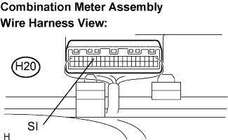
Connect the oscilloscope to the terminal SI (H20-15) and body ground.
-
Start the engine.
-
Check the signal waveform according to the condition(s) in the table below.
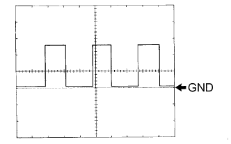
Item Condition Tool setting 5 V/DIV., 10 ms/DIV. Vehicle condition Driving at approx. 20 km/h (12 mph) OK The correct waveform appears as shown in the illustration. Tech Tips
As vehicle speed increases, the cycle of the signal waveform narrows.
-
NG 
INSPECT SPEEDOMETER SENSOR Click here
OK 
REPLACE COMBINATION METER ASSEMBLY
-
-
INSPECT SPEEDOMETER SENSOR
-
Disconnect the connector from the speedometer sensor.
-
Measure the voltage according to the value(s) in the table below.
Standard Voltage Tester Connection Condition Specified Condition D38-1 (IG) - Body ground Turn the ignition switch OFF → ON Below 1 V → 10 to 14 V
NG 
REPAIR OR REPLACE HARNESS OR CONNECTOR
OK 
-
-
CHECK HARNESS AND CONNECTOR (BETWEEN COMBINATION METER AND SPEEDOMETER SENSOR)
-
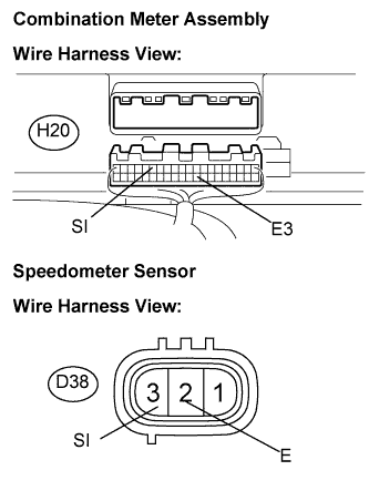
Disconnect H20 and D38 connectors.
-
Measure the resistance according to the value(s) in the table below.
Standard Resistance Tester Connection Condition Specified Condition SI (H20-15) - SI (D38-3) Always Below 1 Ω E3 (H20-29) - E (D38-2) Always Below 1 Ω SI (H20-15) - Body ground Always 10 kΩ or higher
NG
REPAIR OR REPLACE HARNESS OR CONNECTOR
OK
-
-
INSPECT SPEEDOMETER SENSOR
-
Check voltage.
-
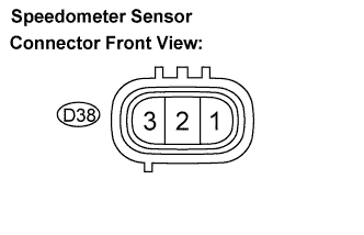
Connect the positive lead (+) from the battery to terminal 1 and negative (-) lead to terminal 2.
-
Connect the positive (+) lead from the tester to terminal 3 and the negative (-) lead to terminal 2.
Standard Voltage Tester Connection Condition Specified Condition IG (D38-1) - Body ground Ignition switch OFF → ON Below 1 V → 10 to 14 V -
Rotate the shaft.
-
Check that there is voltage change from approximately 0 V to 11 V or more between terminals 2 and 3.
Tech Tips
The voltage should change 4 times for every revolution. If the result is not as specified, replace the sensor.
-
NG
REPLACE SPEEDOMETER SENSOR
OK
REPLACE COMBINATION METER ASSEMBLY
-