METER / GAUGE SYSTEM Entire Combination Meter does not Operate
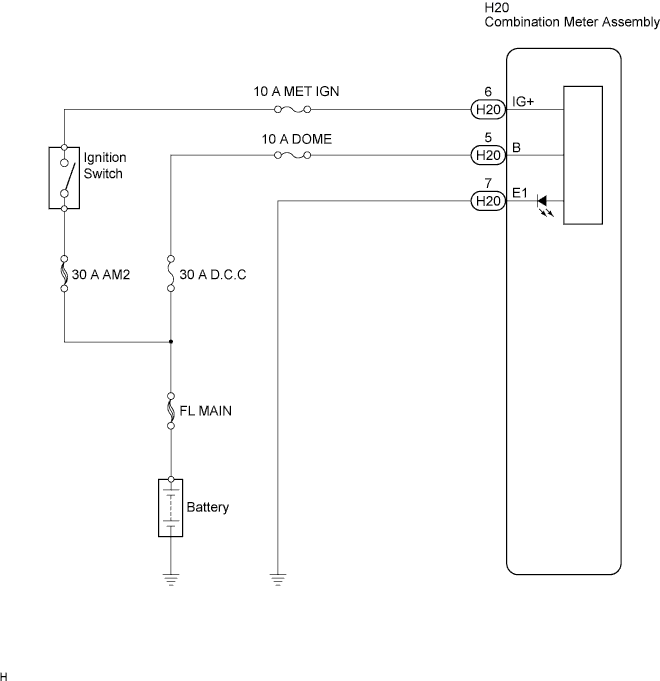
WIRING DIAGRAM
INSPECTION PROCEDURE
PROCEDURE
-
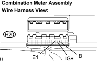
INSPECT COMBINATION METER ASSEMBLY
-
Disconnect the H20 connector.
-
Measure the resistance according to the value(s) in the table below.
Standard Resistance Tester Connection Condition Specified Condition E1 (H20-7) - Body ground Always Below 1 Ω -
Measure the voltage according to the value(s) in the table below.
Standard Voltage Tester Connection Condition Specified Condition B (H20-5) - Body ground Always 10 to 14 V IG+ (H20-6) - Body ground Ignition switch ON 10 to 14 V
NG 
REPAIR OR REPLACE HARNESS OR CONNECTOR
OK 
REPLACE COMBINATION METER ASSEMBLY
-