METER / GAUGE SYSTEM, Diagnostic DTC:B1500

| DTC Code | DTC Name |
|---|---|
| B1500 | Fuel Sender Open Detected |
DESCRIPTION
This DTC is stored when the combination meter detects a fuel sender gauge malfunction.
| DTC Code | DTC Detection Condition | Trouble Area |
|---|---|---|
| B1500 | Both conditions are met:
|
|
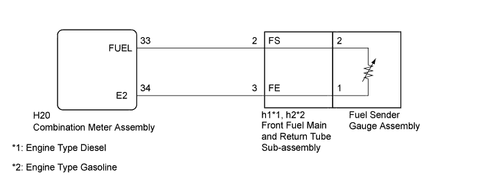
WIRING DIAGRAM
INSPECTION PROCEDURE
Note
Be careful of flames.
PROCEDURE
-
READ VALUE USING GTS (FUEL INPUT)
-
Use the Data List to check if the fuel input signal is operating properly Click here.
Combination Meter Tester Display Measurement Item/Range Normal Condition Diagnostic Note Fuel Input Fuel input signal/Min.: 0, Max. 127.5 Current fuel level displayed Unit: Liters. OK Fuel amount value displayed on the GTS is almost the same as needle indication.
NG 
CHECK HARNESS AND CONNECTOR (COMBINATION METER ASSEMBLY - FRONT FUEL MAIN AND RETURN TUBE SUB-ASSEMBLY AND BODY GROUND) Click here
OK 
REPLACE COMBINATION METER ASSEMBLY Click here
-
-
CHECK HARNESS AND CONNECTOR (COMBINATION METER ASSEMBLY - FRONT FUEL MAIN AND RETURN TUBE SUB-ASSEMBLY AND BODY GROUND)
-
Disconnect the H20 combination meter assembly connector.
-
Disconnect the h1*1 or h2*2 front fuel main and return tube sub-assembly connector.
-
*1: Engine Type Diesel
-
*2: Engine Type Gasoline
-
-
Measure the resistance according to the value(s) in the table below.
Standard Resistance Engine Type Diesel Tester Connection Condition Specified Condition H20-33 (FUEL) - h1-2 Always Below 1 Ω H20-34 (E2) - h1-3 H20-33 (FUEL) or h1-2 - Body ground Always 10 kΩ or higher H20-34 (E2) or h1-3 - Body ground Engine Type Gasoline Tester Connection Condition Specified Condition H20-33 (FUEL) - h1-2 Always Below 1 Ω H20-34 (E2) - h1-3 H20-33 (FUEL) or h1-2 - Body ground Always 10 kΩ or higher H20-34 (E2) or h1-3 - Body ground
NG 
REPAIR OR REPLACE HARNESS OR CONNECTOR
OK 
-
-
INSPECT FRONT FUEL MAIN AND RETURN TUBE SUB-ASSEMBLY
-
Remove the front fuel main and return tube sub-assembly.
-
for 1KD-FTV: Click here
-
for 2KD-FTV: Click here
-
for 5L-E: Click here
-
for 1TR-FE: Click here
-
for 2TR-FE: Click here
-
-
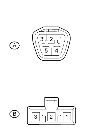
Measure the resistance according to the value(s) in the table below.
Standard Resistance Tester Connection Condition Specified Condition A-2 - B-2 Always Below 1 Ω A-3 - B-1
-
*: Replacement procedure;
-
for 1KD-FTV: Click here
-
for 2KD-FTV: Click here
-
for 5L-E: Click here
-
for 1TR-FE: Click here
-
for 2TR-FE: Click here
-
NG
REPLACE FRONT FUEL MAIN AND RETURN TUBE SUB-ASSEMBLY*
OK
-
-
INSPECT FUEL SENDER GAGE ASSEMBLY
-
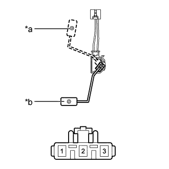
Text in Illustration *a F (Upper) *b E (Lower) Remove the fuel sender gauge assembly.
-
for 1KD-FTV: Click here
-
for 2KD-FTV: Click here
-
for 5L-E: Click here
-
for 1TR-FE: Click here
-
for 2TR-FE: Click here
-
-
Measure the resistance according to the value(s) in the table below.
Standard Resistance Tester Connection Condition Specified Condition 1 - 2 Float level is F (upper) 13.5 to 16.5 Ω Float level is E (lower) 405.5 to 414.5 Ω Tech Tips
*: Replacement procedure;
-
for 1KD-FTV: Click here
-
for 2KD-FTV: Click here
-
for 5L-E: Click here
-
for 1TR-FE: Click here
-
for 2TR-FE: Click here
-
NG
REPLACE FUEL SENDER GAUGE ASSEMBLY*
OK
REPLACE COMBINATION METER ASSEMBLY Click here
-