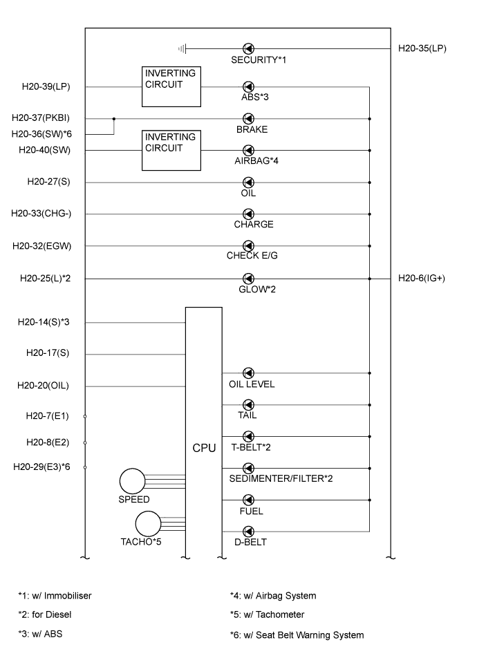
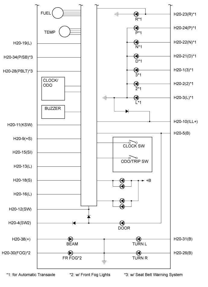
METER / GAUGE SYSTEM TERMINALS OF ECU

-
COMBINATION METER ASSEMBLY
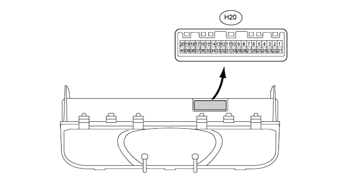
Terminal No. (Symbol) Wiring Color Terminal Description Condition Specified Condition H20-1 (3)*1 - Body ground B - Body ground A/T shift condition signal (3) Ignition switch ON, A/T 3 indicator light OFF → ON Below 1 V → 11 to 14 V H20-2 (2)*1 - Body ground Y - Body ground A/T shift condition signal (2) Ignition switch ON, A/T 2 indicator light OFF → ON Below 1 V → 11 to 14 V H20-3 (L)*1 - Body ground R - Body ground A/T shift condition signal (L) Ignition switch ON, A/T L indicator light OFF → ON Below 1V → 11 to 14 V H20-4 (SW2) - Body ground Y-R - Body ground Except driver side door condition signal Ignition switch ON, except driver side door CLOSE → OPEN 11 to 14 V → Below 1 V H20-5 (B) - Body ground R - Body ground Battery Always 11 to 14 V H20-6 (IG+) - Body ground B-R - Body ground Ignition switch signal Ignition switch OFF → ON Below 1V → 11 to 14 V H20-7 (E1) - Body ground W-B - Body ground Ground Always Below 1 V H20-8 (E2) - Body ground W-B - Body ground Ground (Fuel ground) Always Below 1 V H20-9 (+S) - Body ground P-L - Body ground Speed signal (Output) Ignition switch ON, turn the wheel slowly Pulse generation
(See waveform 1)
H20-10 (ILL+) - Body ground G - Body ground Illumination signal Ignition switch ON, light control switch OFF → TAIL/HEAD Below 1 V → 11 to 14 V H20-11 (KSW) - Body ground Y - Body ground Key switch signal Ignition switch OFF → ON Below 1 V → 11 to 14 V H20-12 (SW) - Body ground R-G - Body ground Driver side door condition signal Ignition switch ON, driver side door CLOSE → OPEN 11 to 14 V → Below 1 V H20-13 (L) - Body ground Y-R - Body ground Fuel signal Ignition switch ON, fuel level is FULL → EMPTY Below 1 V → 4 to 7 V H20-14 (S) - Body ground B-Y - Body ground Tachometer signal Ignition switch ON, engine running Pulse generation
(See waveform 2)
H20-15 (SI) - Body ground P - Body ground Speed signal (Input) Ignition switch ON, engine running Pulse generation
(See waveform 1)
H20-16 (L)*2 - Body ground R-B - Body ground Fuel filter signal Ignition switch ON, FILTER/SEDIMENT indicator light OFF → ON 11 to 14 V → Below 1 V H20-17 (S) - Body ground Y - Body ground Water temperature signal Ignition switch ON, coolant temperature 50°C to 120°C (122°F to 248.0°F) Pulse generation
(See waveform 3)
H20-18 (S)*2 - Body ground LG - Body ground Fuel sedimenter signal Ignition switch ON, FILTER/SEDIMENT indicator light OFF → ON 11 to 14 V → Below 1 V H20-19 (L) - Body ground LG - Body ground Driver side seat belt signal Ignition switch ON, driver side seat belt warning light Blinks → OFF 11 to 14 V → Below 1 V H20-20 (OIL) - Body ground Y-G - Body ground Oil level signal Ignition switch ON, OIL LEVEL indicator light ON → OFF 11 to 14 V → Below 1 V H20-21 (D)*1 - Body ground G-Y - Body ground A/T shift condition signal (D) Ignition switch ON, A/T D indicator light OFF → ON Below 1V → 11 to 14V H20-22 (N)*1 - Body ground GR - Body ground A/T shift condition signal (N) Ignition switch ON, A/T N indicator light OFF → ON Below 1V → 11 to 14V H20-23 (R)*1 - Body ground L - Body ground A/T shift condition signal (R) Ignition switch ON, A/T R indicator light OFF → ON Below 1V → 11 to 14V H20-24 (P)*1 - Body ground R-W - Body ground A/T shift condition signal (P) Ignition switch ON, A/T P indicator light OFF → ON Below 1V → 11 to 14V H20-25 (L)*2 - Body ground B-W - Body ground Glow signal Ignition switch ON, GLOW indicator light OFF → ON Below 1V → 11 to 14V H20-26 (B) - Body ground L-R - Body ground Turn signal flasher R signal Ignition switch ON, turn signal flasher RH OFF → ON Below 1V → 11 to 14V H20-27 (S) - Body ground W - Body ground Oil pressure signal Ignition switch ON, OIL indicator light OFF → ON 11 to 14 V → Below 1 V H20-28 (PBLT)*5 - Body ground B-R - Body ground Seat belt warning signal
(Passenger side)
Ignition switch ON, Front passenger side seat belt warning light OFF → ON →OFF 11 to 14V → Below 1V → 11 to 14V H20-29 (E3)*5 - Body ground BR - Body ground Ground (Speed sensor ground) Always Below 1V H20-30 (FOG) - Body ground Y - Body ground Front fog light signal Ignition switch ON, front fog light OFF → ON Below 1V → 11 to 14V H20-31 (B) - Body ground L - Body ground Turn signal flasher L signal Ignition switch ON, turn signal flasher LH OFF → ON Below 1V → 11 to 14V H20-32 (EGW) - Body ground G-R - Body ground Check engine signal Ignition switch ON, CHECK E/G warning light OFF → ON Below 1V → 11 to 14V H20-33 (CHG-) - Body ground B - Body ground Charge signal Ignition switch ON, CHARGE warning light OFF → ON 11 to 14 V → Below 1 V H20-34 (P/SB) *5 - Body ground W - Body ground Seat belt warning signal
(Passenger side)
Ignition switch ON, Front passenger side seat belt warning light OFF → ON →OFF 11 to 14V → Below 1V → 11 to 14V H20-35 (LP)*4 - Body ground R - Body ground Immobiliser signal Ignition switch OFF, SECURITY indicator light OFF → ON Below 1V → 11 to 14V H20-36 (SW)*5 - Body ground B - Body ground Brake fluid level warning signal Ignition switch ON, BRAKE warning light OFF → ON Below 1V → 11 to 14V H20-37 (PKBI) - Body ground B - Body ground Brake signal Ignition switch ON, BRAKE warning light OFF → ON Below 1V → 11 to 14V H20-38 (+) - Body ground R-B - Body ground R-B - Body ground Ignition switch ON, BEAM indicator light OFF → ON Below 1V → 11 to 14V H20-39 (LP)*2 - Body ground B-R - Body ground ABS signal Ignition switch ON, ABS warning light OFF → ON Below 1V → 11 to 14V H20-40 (SW)*3 - Body ground B-Y - Body ground Airbag signal Ignition switch ON, AIRBAG indicator light OFF → ON Below 1V → 11 to 14V *1: for Automatic Transaxle
*2: for Diesel
*3: Vehicles with Airbag
*4: Vehicles with Immobiliser
*5: Vehicles with Seat Belt Warning Buzzer
-
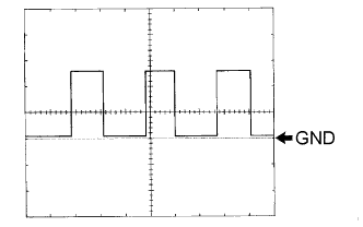
Waveform 1: Using an oscilloscope:
Terminal Connections H20-9 (+S) - Body ground
H20-15 (SI) - Body ground
Tester Range 5 V/DIV., 20 ms/DIV. Vehicle Condition Driving at approx. 20 km/h (12.4 mph) -
Waveform 2: Using an oscilloscope:
Terminal Connections H20-14 (S) - Body ground Tester Range 5 V/DIV., 10 ms/DIV. Vehicle Condition Engine idle speed -
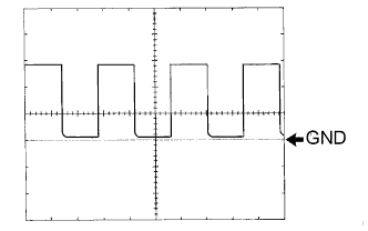
Waveform 3: Using an oscilloscope:
Terminal Connections H20-17 (S) - Body ground Tester Range 5 V/DIV., 100 ms/DIV. Vehicle Condition Ignition switch ON, engine idle speed
Tech Tips
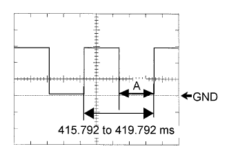
As engine coolant temperature rises, the period A shown in the illustration becomes longer.
Except Middle East Engine Coolant Temperature A Less than 50°C (122.0°F) 96.304 to 100.304 ms 83°C (181.4°F) 231.472 to 235.472 ms 120°C (248.0°F) 383.024 to 387.024 ms Middle East Engine Coolant Temperature A Less than 70°C (158.0°F) 178.224 to 182.224 ms 95°C (203.0°F) 282.624 to 286.624 ms 120°C (248.0°F) 383.024 to 387.024 ms -
-
ECM
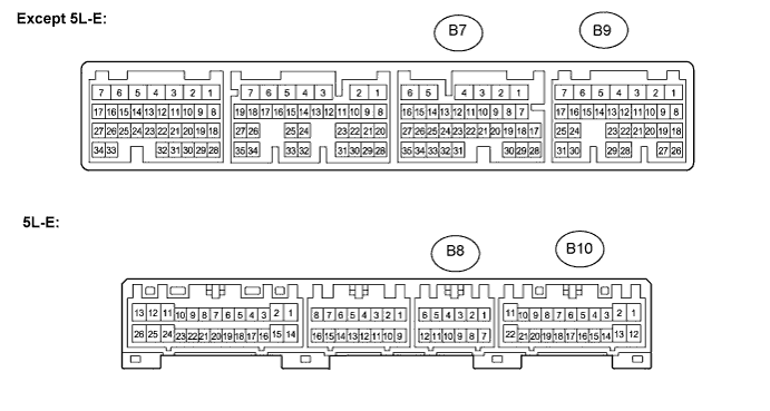
Terminal No. (Symbol) Wiring Color Terminal Description Condition Specified Condition B7-1 (TACH)*1 - Body ground B-Y - Body ground Tachometer signal Ignition switch ON, engine idle speed Pulse generation
(See waveform 1)
B7-14 (THWO)*1 - Body ground Y - Body ground Water temperature signal Ignition switch ON, engine coolant temperature 50°C to 120°C (122°F to 248°F) Pulse generation
(See waveform 2)
B9-4 (TACH)*2 - Body ground B-Y - Body ground Tachometer signal Ignition switch ON, engine idle speed Pulse generation
(See waveform 1)
B9-2 (THWO)*2 - Body ground Y - Body ground Water temperature signal Ignition switch ON, engine coolant temperature 50°C to 120°C (122°F to 248°F) Pulse generation
(See waveform 2)
B8-7 (TAC)*3 - Body ground B-Y - Body ground Tachometer signal Ignition switch ON, engine idle speed Pulse generation
(See waveform 1)
B10-8 (THWO)*3 - Body ground Y - Body ground Water temperature signal Ignition switch ON, engine coolant temperature 50°C to 120°C (122°F to 248°F) Pulse generation
(See waveform 2)
*1: for 2TR-FE
*2: for 1KD-FTV or 2KD-FTV
*3: for 5L-E
-
Waveform 1: Using an oscilloscope:
Terminal Connections B7-1 (TACH)*1 - Body ground
B9-4 (TACH)*2 - Body ground
B8-7 (TAC)*3 - Body ground
Tester Range 5 V/DIV., 10 ms /DIV. Vehicle Condition Engine idle speed *1: for 2TR-FE
*2: for 1KD-FTV or 2KD-FTV
*3: for 5L-E
-
Waveform 2: Using an oscilloscope:
Terminal Connections B7-14 (THWO)*1 - Body ground
B9-2 (THWO)*2 - Body ground
B10-8 (THWO)*3 - Body ground
Tester Range 5 V/DIV., 100 ms /DIV. Vehicle Condition Ignition switch ON, engine idle speed *1: for 2TR-FE
*2: for 1KD-FTV or 2KD-FTV
*3: for 5L-E
Tech Tips
As engine coolant temperature rises, the period A shown in the illustration becomes longer.
Except Middle East Engine Coolant Temperature A Less than 70°C (158.0°F) 178.224 to 182.224 ms 95°C (203.0°F) 282.624 to 286.624 ms 120°C (248.0°F) 383.024 to 387.024 ms Middle East Engine Coolant Temperature A Less than 50°C (122.0°F) 96.304 to 100.304 ms 83°C (181.4°F) 231.472 to 235.472 ms 120°C (248.0°F) 383.024 to 387.024 ms -
-
COMBINATION METER INNER CIRCUIT