FUEL SENDER GAUGE ASSEMBLY INSPECTION

-
INSPECT FUEL SENDER GAUGE ASSEMBLY
-
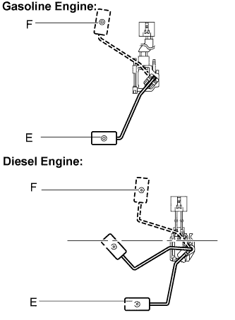
Check that the float moves between F (top) and E (bottom) smoothly.
OK The float moves between F (top) and E (bottom) smoothly. -
Disconnect the h2 (*1)/h1 (*2) connector from the fuel sender gauge.
-
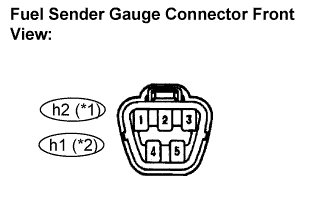
Measure the resistance according to the value(s) in the table below.
Standard Resistance (Gasoline Engine) Tester Connection Condition Specified Condition FUEL SENDER (h2-2) - EARTH (h2-3) F 3.0 to 5.0 Ω FUEL SENDER (h2-2) - EARTH (h2-3) E 107.5 to 112.5 Ω Tester Connection Coniditon Specified Condition FUEL SENDER (h1-2) - EARTH (h1-3) F 3.0 to 5.0 Ω FUEL SENDER (h1-2) - EARTH (h1-3) E 107.5 to 112.5 Ω *1: Gasoline engine
*2: Diesel engine
Tech Tips
If the value is not as specified, replace the fuel sender gauge assemlby.
-