BACK DOOR LOCK INSPECTION

-
INSPECT BACK DOOR LOCK ASSEMBLY
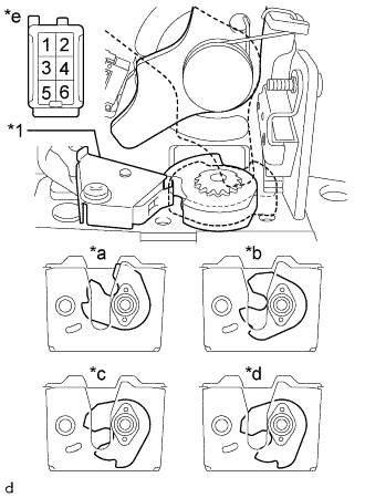
Text in Illustration *1 Half-latch Switch *a Open *b Half-latch *c Full-latch *d Over-latch *e Component without harness connected
(Back Door Lock Assembly)
-
Measure the resistance according to the value(s) in the table below.
-
Check the operation of the half-latch switch.
Standard Resistance Tester Connection Condition Specified Condition 3 - 6 Open Below 1 Ω 3 - 6 Half-latch 10 kΩ or higher 3 - 6 Full-latch 10 kΩ or higher 3 - 6 Over-latch 10 kΩ or higher If the result is not as specified, replace the back door lock assembly.
-
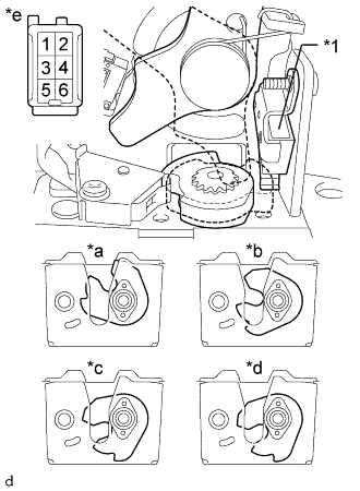
Text in Illustration *1 Full-latch Switch *a Open *b Half-latch *c Full-latch *d Over-latch *e Component without harness connected
(Back Door Lock Assembly)
Check the operation of the full-latch switch.
Standard Resistance Tester Connection Condition Specified Condition 5 - 6 Open 10 kΩ or higher 5 - 6 Half-latch 10 kΩ or higher 5 - 6 Full-latch 10 kΩ or higher 5 - 6 Over-latch Below 1 Ω If the result is not as specified, replace the back door lock assembly.
-
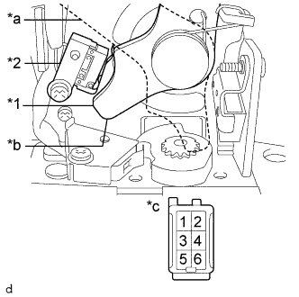
Text in Illustration *1 Back Door Lock Control Close Lever *2 Initial Position Switch *a Back Door Lock Control Close Lever (Lock) *b Back Door Lock Control Close Lever (Release) *c Component without harness connected
(Back Door Lock Assembly)
Check the operation of the initial position switch.
Standard Resistance Tester Connection Condition Specified Condition 4 - 6 Back Door Lock Control Close Lever (Lock) Below 1 Ω 4 - 6 Back Door Lock Control Close Lever (Release) 10 kΩ or higher If the result is not as specified, replace the back door lock assembly.
-
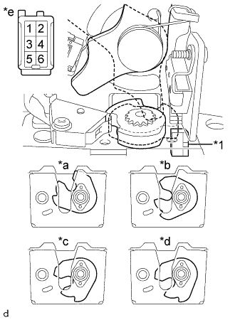
Text in Illustration *1 Courtesy Switch *a Open *b Half-latch *c Full-latch *d Over-latch *e Component without harness connected
(Back Door Lock Assembly)
Check the operation of the courtesy switch.
Standard Resistance Tester Connection Condition Specified Condition 1 - 2 Open Below 1 Ω 1 - 2 Half-latch Below 1 Ω 1 - 2 Full-latch 10 kΩ or higher 1 - 2 Over-latch 10 kΩ or higher If the result is not as specified, replace the back door lock assembly.
-
-
-
INSPECT BACK DOOR CLOSER MOTOR ASSEMBLY
-
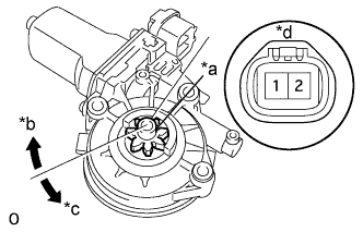
Text in Illustration *a Back door closer motor gear *b Clockwise *c Counterclockwise *d Component without harness connected
(Back Door Closer Motor Assembly)
Check that the motor gear rotates smoothly as follows.
OK Measurement Condition Specified Condition Battery positive (+) → 1
Battery negative (-) → 2
Back door closer motor gear rotates clockwise Battery positive (+) → 2
Battery negative (-) → 1
Back door closer motor gear rotates counterclockwise If the result is not as specified, replace the back door closer motor assembly.
-
-
INSPECT BACK DOOR REMOTE CONTROL ASSEMBLY
-
Check the operation of the back door remote control assembly.
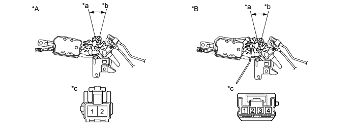
Text in Illustration *A w/o Smart Entry and Start System *B w/ Smart Entry and Start System *a Lock *b Unlock *c Component without harness connected
(Back Door Remote Control Assembly)
- -
-
Apply battery voltage and check operation of the back door remote control assembly.
OK w/o Smart Entry and Start System: Measurement Condition Specified Condition Battery positive (+) → Terminal 1
Battery negative (-) → Terminal 2
Unlock Battery positive (+) → Terminal 2
Battery negative (-) → Terminal 1
Lock OK w/ Smart Entry and Start System: Measurement Condition Specified Condition Battery positive (+) → Terminal 3
Battery negative (-) → Terminal 2
Unlock Battery positive (+) → Terminal 2
Battery negative (-) → Terminal 3
Lock -
w/ Smart Entry and Start System:
Check the position switch.
Standard Resistance Tester Connection Condition Specified Condition 1 - 4 Lock 10 kΩ or higher 1 - 4 Unlock Below 1 Ω If the result is not as specified, replace the back door remote control assembly.
-
-