REAR DOOR LOCK INSPECTION

-
INSPECT REAR DOOR LOCK ACTUATOR ASSEMBLY LH
-
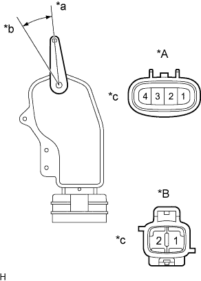
Text in Illustration *A w/ Power Slide Door *B w/o Power Slide Door *a Lock *b Unlock *c Component without harness connected
(Door Lock Actuator Assembly)
Inspect the slide door lock assembly LH.
-
Apply battery voltage and check operation of the door lock actuator.
Standard w/ Power Slide Door Measurement Condition Specified Condition Battery positive (+) → Terminal 2
Battery negative (-) → Terminal 3
Lock Battery positive (+) → Terminal 3
Battery negative (-) → Terminal 2
Unlock w/o Power Slide Door Measurement Condition Specified Condition Battery positive (+) → Terminal 1
Battery negative (-) → Terminal 2
Lock Battery positive (+) → Terminal 2
Battery negative (-) → Terminal 1
Unlock
-
-
w/ Smart Entry and Start System:
Check the operation of the door unlock detection switch.
-
Measure the resistance according to the value(s) in the table below.
Standard resistance Tester Connection Condition Specified Condition Battery positive (+) → Terminal 1 (*A)
Battery negative (-) → Terminal 4 (*A)
Locks 10 kΩ or higher Battery positive (+) → Terminal 1 (*A)
Battery negative (-) → Terminal 4 (*A)
Unlocks Below 1 Ω
-
-
-
INSPECT REAR DOOR LOCK ACTUATOR ASSEMBLY RH
-
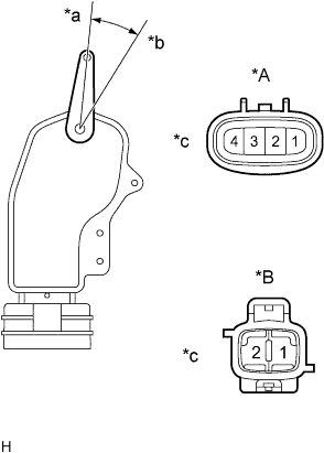
Text in Illustration *A w/ Power Slide Door *B w/o Power Slide Door *a Lock *b Unlock *c Component without harness connected
(Door Lock Actuator Assembly)
Inspect the slide door lock assembly RH.
-
Apply battery voltage and check operation of the door lock actuator.
Standard w/ Power Slide Door Measurement Condition Specified Condition Battery positive (+) → Terminal 2
Battery negative (-) → Terminal 3
Lock Battery positive (+) → Terminal 3
Battery negative (-) → Terminal 2
Unlock w/o Power Slide Door Measurement Condition Specified Condition Battery positive (+) → Terminal 1
Battery negative (-) → Terminal 2
Lock Battery positive (+) → Terminal 2
Battery negative (-) → Terminal 1
Unlock
-
-
w/ Smart Entry and Start System:
Check the operation of the door unlock detection switch.
-
Measure the resistance according to the value(s) in the table below.
Standard resistance Tester Connection Condition Specified Condition Battery positive (+) → Terminal 1 (*A)
Battery negative (-) → Terminal 4 (*A)
Locks 10 kΩ or higher Battery positive (+) → Terminal 1 (*A)
Battery negative (-) → Terminal 4 (*A)
Unlocks Below 1 Ω
-
-