KEY REMINDER WARNING SYSTEM TERMINALS OF ECU

-
COMBINATION METER ASSEMBLY
-
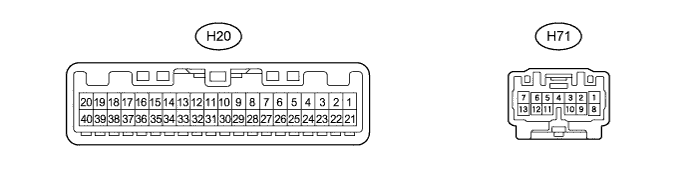
Disconnect the H20 combination meter assembly connector.
-
Measure the voltage and resistance according to the value(s) in the table below.
Terminal No. (Symbol) Wiring Color Terminals Description Condition Specified Condition H20-1 (L) - Body ground R - Body ground +B power supply Always 11 to 14 V H20-2 (IG+) - Body ground B - Body ground Ignition switch (IG) signal Ignition switch off → ON Below 1 V → 11 to 14 V H20-4 (DCTY) - Body ground G - Body ground Front door courtesy light switch (Driver side) input Front driver side door closed → Open 10 kΩ or higher → Below 1 Ω H20-9 (KEYE) - Body ground Y - Body ground Key unlock warning switch input No key in ignition key cylinder → Key inserted 10 kΩ or higher → Below 1 Ω H20-21 (E1) - Body ground W-B - Body ground Ground Always Below 1 Ω -