SMART ENTRY AND START SYSTEM (for Entry Function), Diagnostic DTC:B27B0

| DTC Code | DTC Name |
|---|---|
| B27B0 | Lost Communication with MainBody Module |
DESCRIPTION
The certification ECU (smart key ECU assembly) and instrument panel junction block assembly (body computer) communicate using unidirectional communication lines.
This DTC is output when the certification ECU (smart key ECU assembly) sends a request to the instrument panel junction block assembly (body computer) but does not receive a reply.
| DTC Code | DTC Detection Condition | Trouble Area | DTC Output Confirmation Operation |
|---|---|---|---|
| B27B0 | Certification ECU (smart key ECU assembly) sends request but instrument panel junction block assembly (body computer) does not reply within 10 seconds (1 trip detection logic*). |
|
Driver door open/close |
-
*: Only output while a malfunction is present.
| Vehicle Condition when Malfunction Detected | Fail-safe Operation when Malfunction Detected |
|---|---|
|
- |
| DTC Code | Data List and Active Test |
|---|---|
| B27B0 | Key diagnostic mode can be used to perform troubleshooting |
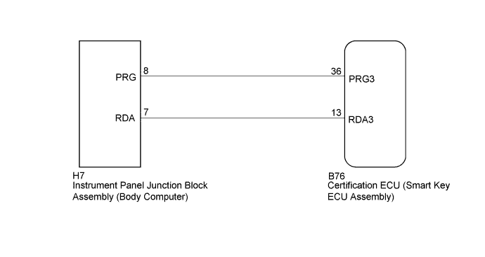
WIRING DIAGRAM
INSPECTION PROCEDURE
Note
-
The smart entry and start system (for Entry Function) uses a multiplex communication system (LIN communication system) and the CAN communication system. Inspect the communication function by following How to Proceed with Troubleshooting Click here. Troubleshoot the smart entry and start system (for Entry Function) after confirming that the communication systems are functioning properly.
-
When using the GTS with the vehicle engine switch off, connect the GTS to the vehicle and turn a courtesy light switch on and off at intervals of 1.5 seconds or less until communication between the GTS and the vehicle begins. Then select the Model Code "KEY REGIST" under manual mode and enter the following menus: Body Electrical / Entry&Start(CAN). While using the GTS, periodically turn a courtesy light switch on and off at intervals of 1.5 seconds or less to maintain communication between the GTS and the vehicle.
-
Before replacing the certification ECU (smart key ECU assembly), refer to the smart entry and start system (for Entry Function) precaution Click here.
-
After repair, confirm that no DTCs are output by performing the "DTC Output Confirmation Operation".
PROCEDURE
-
CHECK HARNESS AND CONNECTOR (CERTIFICATION ECU [SMART KEY ECU ASSEMBLY] - INSTRUMENT PANEL JUNCTION BLOCK ASSEMBLY)
-
Disconnect the B76 certification ECU (smart key ECU assembly) connector.
-
Disconnect the H7 instrument panel junction block assembly (body computer) connector.
-
Measure the resistance according to the value(s) in the table below.
Standard Resistance Tester Connection Condition Specified Condition B76-36 (PRG3) - H7-8 (PRG) Always Below 1 Ω B76-13 (RDA3) - H7-7 (RDA) Always Below 1 Ω B76-36 (PRG3) or H7-8 (PRG) - Body ground Always 10 kΩ or higher B76-13 (RDA3) or H7-7 (RDA) - Body ground Always 10 kΩ or higher -
Connect the B76 certification ECU (smart key ECU assembly) connector.
-
Connect the H7 instrument panel junction block assembly (body computer) connector.
NG 
REPAIR OR REPLACE HARNESS OR CONNECTOR
OK 
-
-
CLEAR DTC
-
Clear the DTCs Click here.
NEXT
-
-
CHECK FOR DTC
-
Open and close the driver door.
-
Check for DTCs Click here.
OK DTC B27B0 is not output.
NG 
REPLACE INSTRUMENT PANEL JUNCTION BLOCK ASSEMBLY (BODY COMPUTER) Click here
OK 
END (CONNECTOR WAS NOT CONNECTED PROPERLY)
-
-
REPLACE INSTRUMENT PANEL JUNCTION BLOCK ASSEMBLY (BODY COMPUTER)
-
Replace the instrument panel junction block assembly (body computer) with a new or known good one.
NEXT
-
-
CLEAR DTC
-
Clear the DTCs Click here.
NEXT
-
-
CHECK FOR DTC
-
Open and close the driver door.
-
Check for DTCs Click here.
OK DTC B27B0 is not output.
NG
REPLACE CERTIFICATION ECU (SMART KEY ECU ASSEMBLY)
OK
END (INSTRUMENT PANEL JUNCTION BLOCK ASSEMBLY [BODY COMPUTER] WAS DEFECTIVE)
-