WIRELESS DOOR LOCK CONTROL SYSTEM (w/o Smart Entry and Start System) Only Wireless Control Function is Inoperative
DESCRIPTION
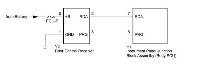
The door control receiver receives signals from the door control transmitter assembly and sends this signal to the instrument panel junction block assembly (body ECU). Then, instrument panel junction block assembly (body ECU) drives a door lock motor on each door and operate lock/unlock control.
WIRING DIAGRAM
INSPECTION PROCEDURE
Note
Inspect the fuses for circuits related to this system before performing the following procedure.
PROCEDURE
-
CHECK POWER DOOR LOCK OPERATION
-
When the door control switch is operated, check that the locked doors unlock.
OK The locked doors unlock.
NG 
GO TO POWER DOOR LOCK CONTROL SYSTEM Click here
OK 
-
-
CHECK KEY REMINDER WARNING SYSTEM
-
Check that the key reminder warning buzzer operates normally Click here.
OK The key reminder warning buzzer operates normally.
NG
GO TO KEY REMINDER WARNING SYSTEM Click here
OK
-
-
CHECK DOOR CONTROL TRANSMITTER ASSEMBLY
-
When a known good registered door control transmitter assembly is used, check that the wireless functions operate normally.
OK Wireless door lock/unlock function operates normally with a known good door control transmitter assembly.
NG 
CHECK FOR ELECTRICAL NOISE Click here
OK
-
-
CHECK TRANSMITTER BATTERY
-
Inspect the transmitter battery Click here.
NG
REPLACE TRANSMITTER BATTERY Click here
OK 
REPLACE DOOR CONTROL TRANSMITTER ASSEMBLY
-
-
CHECK FOR ELECTRICAL NOISE
-
Move the door control transmitter assembly in the vicinity of the door control receiver.
Tech Tips
Refer to Parts Location for the location of the door control receiver Click here.
-
Press and hold either the lock or unlock switch on door control transmitter assembly for 1 second and check that the doors lock or unlock accordingly.
OK Wireless door lock control functions operate normally. Tech Tips
-
Check if electrical noise is the cause by moving the door control transmitter assembly closer to the door control receiver. Moving it closer will decrease the effects of electrical noise.
-
If the operation check can be performed normally, there is a high probability that electrical noise or a decrease in output from the door control transmitter assembly is the cause of the malfunction. There is a high probability that electrical noise is the cause if the problem occurs only in a certain location or only during a certain time of day. Also, custom components may be causing electrical noise. If custom components are installed in the vehicle, remove them and perform the operation check again.
-
NG
FIND CAUSE OF ELECTRICAL NOISE AND REMOVE IT
OK
-
-
SWITCH TO SELF DIAGNOSTIC MODE
Note
If the change to the self-diagnostic mode fails, the system will return to the normal mode.
-
Close the driver side door and ensure that the door lock knob is in the unlock position.
-
Insert the door control transmitter assembly into the ignition key cylinder and remove it.
-
Within 5 seconds after the door control transmitter is removed, insert it into the ignition key cylinder again.
-
Turn the ignition switch to the ON position and then off.
-
Within 30 seconds of turning the ignition switch off, turn the ignition switch to the ON position then off 9 times.
Tech Tips
-
Turning the ignition switch to the ON position after the procedure above has been completed will end the self-diagnostic mode.
-
Do not lock or unlock doors while performing the self-diagnostic mode.
-
-
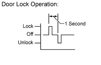
Check that the system has changed to self-diagnostic mode by checking the door lock operation (lock → unlock) as shown in the illustration.
NEXT
-
-
CHECK BY SELF DIAGNOSTIC MODE
-
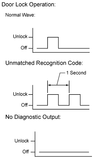
Check the diagnostic outputs when the door control transmitter assembly switch is held down. The diagnostic outputs can be checked by the door lock operating patterns shown in the illustration.
Result Result Proceed to Normal waves are output A Unmatching recognition code is output B No diagnostic outputs C
B
REGISTER RECOGNITION CODE Click here
C
CHECK RESPONSE OF DOOR CONTROL RECEIVER Click here
A
REPLACE INSTRUMENT PANEL JUNCTION BLOCK ASSEMBLY (BODY ECU)
-
-
REGISTER RECOGNITION CODE
-
Check that the system can be switched to rewrite mode or add mode, and that a recognition code can be registered Click here.
OK The system can be switched to rewrite mode or add mode, and that a recognition code can be registered
NG
REPLACE DOOR CONTROL RECEIVER Click here
OK
END (PERFORM OPERATION CHECK)
-
-
CHECK RESPONSE OF DOOR CONTROL RECEIVER
-
Check that the mismatch recognition code is output when the new or normally functioning another vehicle door control transmitter is pressed and hold down.
OK Unmatching recognition code is output.
NG
REPLACE DOOR CONTROL TRANSMITTER ASSEMBLY
OK
-
-
CHECK HARNESS AND CONNECTOR (DOOR CONTROL RECEIVER - BATTERY AND BODY GROUND)
-
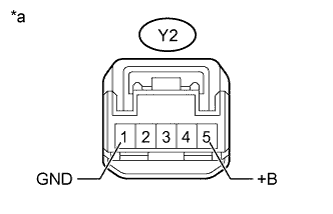
Text in Illustration *a Front view of wire harness connector
(to Door Control Receiver)
Disconnect the door control receiver connector.
-
Measure the resistance according to the value(s) in the table below.
Standard Resistance Tester Connection Condition Specified Condition Y2-1 (E) - Body ground Always Below 1 Ω -
Measure the voltage according to the value(s) in the table below.
Standard Voltage Tester Connection Condition Specified Condition Y2-5 (+B) - Body ground Always 11 to 14 V
NG
REPAIR OR REPLACE HARNESS OR CONNECTOR
OK
-
-
CHECK DOOR CONTROL RECEIVER (OUTPUT SIGNAL)
-
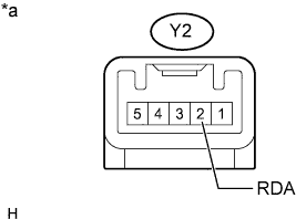
Text in Illustration *a Component with harness connected
(Door Control Receiver)
Reconnect the door control receiver connector.
-
Measure the voltage according to the value(s) in the table below.
Standard Voltage Tester Connection Condition Specified Condition Y2-2 (RDA) - Body ground No key in ignition key cylinder, all doors closed and transmitter switch off → on Pulse generation
NG
REPLACE DOOR CONTROL RECEIVER Click here
OK
-
-
CHECK HARNESS AND CONNECTOR (DOOR CONTROL RECEIVER - INSTRUMENT PANEL JUNCTION BLOCK ASSEMBLY [BODY ECU])
-
Disconnect the Y2 door control receiver connector.
-
Disconnect the H7 instrument panel junction block assembly (body ECU) connector.
-
Measure the resistance according to the value(s) in the table below.
Standard Resistance Tester Connection Condition Specified Condition Y2-2 (RDA) - H7-7 (RDA) Always Below 1 Ω Y2-3 (PRG) - H7-8 (PRG) Always Below 1 Ω Y2-2 (RDA) - Body ground Always 10 kΩ or higher Y2-3 (PRG) - Body ground Always 10 kΩ or higher
NG
REPAIR OR REPLACE HARNESS OR CONNECTOR
OK
-
-
REPLACE DOOR CONTROL RECEIVER
-
Replace the door control receiver with a new or known good one Click here.
NEXT
-
-
REGISTER RECOGNITION CODE
-
Check that the system can be switched to rewrite mode or add mode, and that a recognition code can be registered Click here.
OK The system can be switched to rewrite mode or add mode, and that a recognition code can be registered
NG
REPLACE INSTRUMENT PANEL JUNCTION BLOCK ASSEMBLY (BODY ECU)
OK
REPLACE END (PERFORM OPERATION CHECK)
-