WIRELESS DOOR LOCK CONTROL SYSTEM (w/ Smart Entry and Start System) No Answer-Back
DESCRIPTION
In some cases, wireless door lock control functions are normal but the hazard warning light and/or wireless door lock buzzer answer-back function does not operate. In such cases, hazard warning light signal and/or wireless door lock buzzer outputs may be malfunctioning.
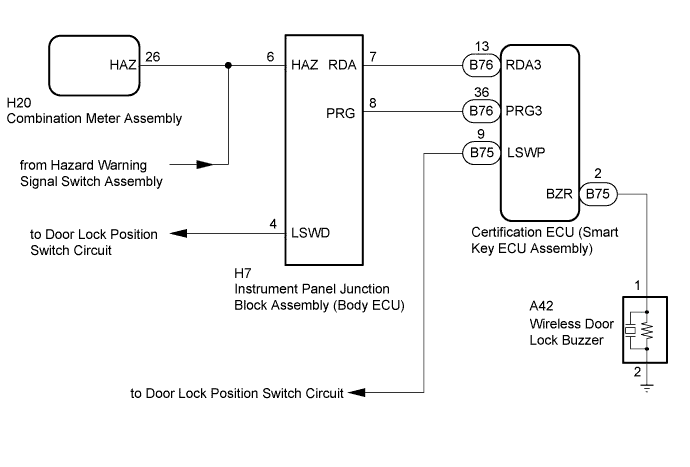
WIRING DIAGRAM
INSPECTION PROCEDURE
Note
-
The wireless door lock system (w/ Smart Entry and Start System) uses the CAN communication system and LIN communication system. First inspect the communication systems by following How to Proceed with Troubleshooting Click here. Troubleshoot the wireless door lock system (w/ Smart Entry and Start System)) after confirming that the communication systems are functioning properly.
-
When replacing the certification ECU (smart key ECU assembly), refer to Service Bulletin.
-
Before performing the inspection, check that DTC B1242 and B27B0 is not output.
PROCEDURE
-
CHECK WIRELESS DOOR LOCK CONTROL FUNCTIONS
-
Check the wireless door lock control function using the electrical key transmitter sub-assembly Click here.
Result Result Proceed to Wireless door lock/unlock operates properly. A Wireless door lock/unlock does not operate properly. B
B 
GO TO SMART ENTRY AND START SYSTEM (for Entry Function) (All Door Entry Lock/Unlock Functions and Wireless Functions) Click here
A 
-
-
CHECK SMART ENTRY AND START SYSTEM
-
Check the smart entry and start function using the electrical key transmitter sub-assembly Click here.
Tech Tips
When the only entry unlock function cannot be operated, there may be a malfunction on the lock position switch circuit
OK Entry unlock operates normally.
NG
GO TO SMART ENTRY AND START SYSTEM (for Entry Function) (How to Proceed with Troubleshooting) Click here
OK
-
-
CHECK CUSTOMIZE CONDITION
-
Check the customize setting Click here.
Result Result Proceed to Wireless Buzzer Volume Setting is set except "OFF" and "Level0(Mute)" A Wireless Buzzer Volume Setting is set "OFF" and "Level0(Mute)" B
B
SET ITEM EXCEPT "OFF" AND "Level0(Mute)"
A
-
-
CHECK ANSWER-BACK FUNCTION
-
Check the wireless answer-back operation using the electrical key transmitter sub-assembly.
Result Result Proceed to Only hazard warning light answer-back does not occur. A Only wireless door lock buzzer answer-back does not occur. B
B 
CHECK HARNESS AND CONNECTOR CERTIFICATION ECU [SMART KEY ECU ASSEMBLY] - WIRELESS DOOR LOCK BUZZER AND BODY GROUND) Click here
A
-
-
CHECK HAZARD WARNING LIGHTS
-
Check that the hazard warning lights blink when the hazard warning signal switch assembly is pressed.
OK The hazard warning lights blink when the hazard warning signal switch assembly is pressed.
NG
GO TO LIGHTING SYSTEM (PROCEED TO HAZARD WARNING SWITCH CIRCUIT) Click here
OK
-
-
CHECK HARNESS AND CONNECTOR (INSTRUMENT PANEL JUNCTION BLOCK ASSEMBLY [BODY ECU] - COMBINATION METER ASSEMBLY)
-
Disconnect the H7 instrument panel junction block assembly connector.
-
Disconnect the H20 combination meter assembly connector.
-
Measure the resistance according to the value(s) in the table below.
Standard Resistance Tester Connection Condition Specified Condition H7-6 (HAZ) - H20-26 (HAZ) Always Below 1 Ω H7-6 (HAZ) or H20-26 (HAZ) - Body ground Always 10 kΩ or higher
NG
REPAIR OR REPLACE HARNESS OR CONNECTOR
OK 
REPLACE INSTRUMENT PANEL JUNCTION BLOCK ASSEMBLY (BODY ECU)
-
-
CHECK HARNESS AND CONNECTOR CERTIFICATION ECU [SMART KEY ECU ASSEMBLY] - WIRELESS DOOR LOCK BUZZER AND BODY GROUND)
-
Disconnect the B75 certification ECU (smart key ECU assembly) connector.
-
Disconnect the A42 wireless door lock buzzer connector.
-
Measure the resistance according to the value(s) in the table below.
Standard Resistance Tester Connection Condition Specified Condition B75-2 (BZR) - A42-1 Always Below 1 Ω A42-2 - Body ground Always Below 1 Ω B75-2 (BZR) or A42-1 - Body ground Always 10 kΩ or higher
NG
REPAIR OR REPLACE HARNESS OR CONNECTOR
OK
-
-
CHECK WIRELESS DOOR LOCK BUZZER
-
Temporally replacing the wireless door lock buzzer with known new or normally functioning one Click here.
-
Check the operation of the wireless answer-back function Click here.
OK Wireless answer-back function operates normally.
NG
REPLACE INSTRUMENT PANEL JUNCTION BLOCK ASSEMBLY (BODY ECU)
OK
END (WIRELESS DOOR LOCK BUZZER WAS DEFECTIVE)
-