WIRELESS DOOR LOCK CONTROL SYSTEM (w/ Smart Entry and Start System) TERMINALS OF ECU

-
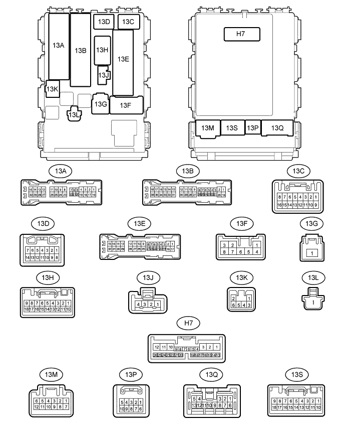
INSTRUMENT PANEL JUNCTION BLOCK ASSEMBLY (BODY ECU)
-
Disconnect the 13B, 13C, 13E, 13G and H7 instrument panel junction block assembly (body ECU) connectors.
-
Measure the resistance and voltage according to the value(s) in the table below.
Terminal No. (Symbol) Wiring Color Terminal Description Condition Specified Condition 13B-3 (L2) - Body ground W - Body ground Door lock key switch signal Front RH door lock key switch off → On (unlock) 10 kΩ or higher → Below 1 Ω 13B-4 (UL2) - Body ground Y - Body ground Door lock key switch signal Front RH door lock key switch off → On (lock) 10 kΩ or higher → Below 1 Ω 13B-5 (UL1) - Body ground Y - Body ground Door lock manual switch signal Driver side door control switch off → on (unlock) 10 kΩ or higher → Below 1 Ω 13B-6 (L1) - Body ground W - Body ground Door lock manual switch signal Driver side door control switch off → On (lock) 10 kΩ or higher → Below 1 Ω 13B-21 (L2) - Body ground W - Body ground Door lock key switch signal Front LH door lock key switch off → On (unlock) 10 kΩ or higher → Below 1 Ω 13B-22 (UL2) - Body ground Y - Body ground Door lock key switch signal Front LH door lock key switch off → On (lock) 10 kΩ or higher → Below 1 Ω 13C-4 (IG) - Body ground B - Body ground Ignition power supply Engine switch off → On (IG) Below 1 V → 11 to 14 V 13E-12 (GND) - Body ground W-B - Body ground Ground Always Below 1 Ω 13G-1 (BECU) - Body ground B-G - Body ground Battery power supply Always 11 to 14 V H7-4 (LSWD) - Body ground W - Body ground Front door lock detection switch RH signal Front door lock RH lock → Unlock 10 kΩ or higher → Below 1 Ω -
Reconnect the 13B, 13C, 13E, 13G and H7 instrument panel junction block assembly (body ECU) connectors.
-
Measure the voltage according to the value(s) in the table below.
Terminal No. (Symbols) Wiring Color Terminal Description Condition Specified Condition 13A-10 (ACT+) - Body ground L - Body ground Back door lock motor drive signal Back door control switch off → On (lock) Below 1 V → 11 to 14 V → Below 1 V 13A-18 (RRCY) - Body ground W - Body ground Rear door courtesy light switch assembly RH signal Rear door RH door closed → Open
-
11 to 14 V* → Below 1 V
-
Pulse generation* → Below 1 V
13A-24 (RRCY) - Body ground W - Body ground Back door courtesy light switch signal Back door door closed → Open
-
11 to 14 V* → Below 1 V
-
Pulse generation* → Below 1 V
13A-29 (ACT-) - Body ground R - Body ground Back door lock motor drive signal Back door control switch off → On (unlock) Below 1 V → 11 to 14 V → Below 1 V 13A-30 (RRCY) - Body ground W - Body ground Rear door courtesy light switch assembly LH signal Rear door LH door closed → Open
-
11 to 14 V* → Below 1 V
-
Pulse generation* → Below 1 V
13B-17 (ACT+) - Body ground L - Body ground Front door lock motor LH/RH drive signal Door control switch off → On (lock) Below 1 V → 11 to 14 V → Below 1 V 13B-35 (ACT-) - Body ground R - Body ground Front door lock motor LH/RH drive signal Door control switch off → On (unlock) Below 1 V → 11 to 14 V → Below 1 V 13E-26 (ACT+) - Body ground L - Body ground Slide door lock motor LH/RH drive signal Slide door lock control switch off → On (lock) Below 1 V → 11 to 14 V → Below 1 V 13E-27 (ACT-) - Body ground R - Body ground Slide door lock motor LH/RH drive signal Slide door lock control switch off → On (unlock) Below 1 V → 11 to 14 V → Below 1 V 13E-10 (PCTY) - Body ground R - Body ground Front door courtesy light switch assembly LH signal Front passenger side door closed → Open
-
11 to 14 V*3 → Below 1 V
-
Pulse generation*3 → Below 1 V
13E-11 (DCTY) - Body ground G - Body ground Front door courtesy light switch assembly RH signal Driver side door closed → Open
-
11 to 14 V* → Below 1 V
-
Pulse generation* → Below 1 V
H7-6 (HAZ) - Body ground W - Body ground Hazard warning light signal Hazard warning signal switch off → On 11 to 14 V → Below 1 V H7-7 (RDA) - Body ground W - Body ground Signal input to certification ECU (smart key ECU assembly)
-
Engine switch off
-
All doors closed
-
All doors locked
Procedure:
11 to 14 V
-
Engine switch off
-
All doors closed
-
10 seconds elapsed after all doors locked
-
Electrical key transmitter subassembly unlock switch pressed
Procedure:
Pulse generation H7-8 (PRG) - Body ground B - Body ground Signal output to certification ECU (smart key ECU assembly)
-
Engine switch off
-
All doors closed
-
All doors locked
Procedure:
11 to 14 V
-
Engine switch off
-
All doors closed
-
10 seconds elapsed after all doors locked
-
Electrical key transmitter subassembly unlock switch pressed
Procedure:
Pulse generation
-
*: The specified value changes depending on vehicle conditions.
-
-
-
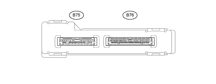
CERTIFICATION ECU (SMART KEY ECU ASSEMBLY)
-
Disconnect the B75 certification ECU (smart key ECU assembly) connector.
-
Measure the resistance and voltage according to the value(s) in the table below.
Terminal No. (Symbol) Wiring Color Terminal Description Condition Specified Condition B75-1 (+B) - Body ground L - Body ground Battery power supply Always 11 to 14 V B75-10 (E) - Body ground W-B - Body ground Ground Always Below 1 Ω -
Reconnect the B75 certification ECU (smart key ECU assembly) connector.
-
Measure the voltage according to the value(s) in the table below.
Terminal No. (Symbols) Wiring Color Terminal Description Condition Specified Condition B75-2 (BZR) - B75-10 (E) B - W-B Wireless door lock buzzer signal Wireless door lock buzzer off Below 1 V Wireless door lock buzzer on Pulse generation B75-20 (IG1D) - B75-10 (E) B - W-B IG Power supply Engine switch off → On (IG) Below 1 V → 9 to 14 V B75-21 (ACCD) - B75-10 (E) R - W-B ACC Power supply Engine switch off → On (ACC) Below 1 V → 9 to 14 V B76-13 (RDA3) - Body ground W - Body ground Signal output to instrument panel junction block assembly (body ECU)
-
Engine switch off
-
All doors closed
-
All doors locked
Procedure:
11 to 14 V
-
Engine switch off
-
All doors closed
-
10 seconds elapsed after all doors locked
-
Electrical key transmitter subassembly unlock switch pressed
Procedure:
Pulse generation B76-38 (PRG3) - Body ground B - Body ground Signal input to instrument panel junction block assembly (body ECU)
-
Engine switch off
-
All doors closed
-
All doors locked
Procedure:
11 to 14 V
-
Engine switch off
-
All doors closed
-
10 seconds elapsed after all doors locked
-
Electrical key transmitter subassembly unlock switch pressed
Procedure:
Pulse generation -
-